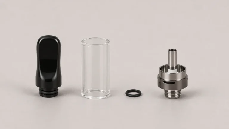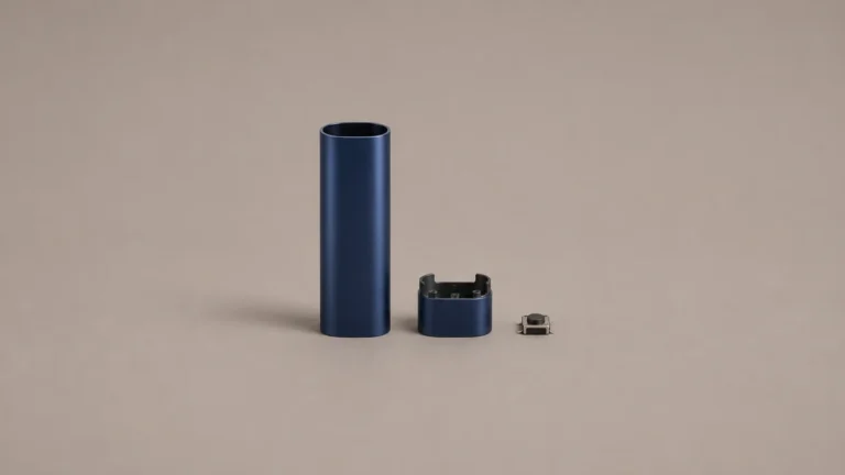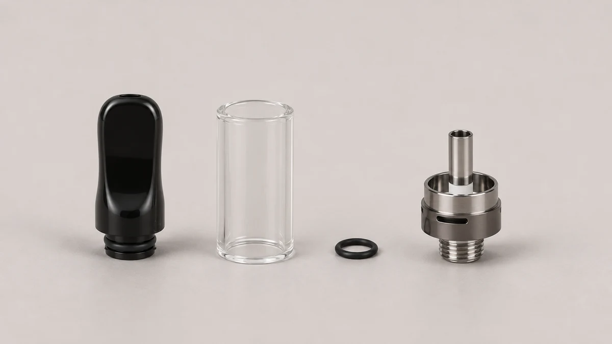
🔍 1. Why Closure and Seal Documentation Belongs in the Drawing Set
A CBD oil vape pen can have two versions that look alike in a photograph but use different mouthpiece closures. For a custom design, ask for a section view that shows where the mouthpiece seats and where the seal sits. Those two locations may be different even if the outside shows only one visible line.
When a product-development conversation starts from a photo of an inert, empty cartridge, the questions that matter are about construction: is the mouthpiece pressed on, threaded on, or snapped into a retaining lip, and does the seam visible on the outside line up with where an internal seal actually sits.
📐 1.1 What a Cross-Section Establishes That a Photo Cannot
A section view can show the cavity, the mouthpiece seat and a seal groove if the design has one. It is especially useful when the view runs through the actual attachment. A drawing that passes through an unrelated part of the shell may leave the most important joint out of view.
Two cartridges can look identical from the outside — same shell diameter, same mouthpiece profile, same seam line — while one seats its seal against a shoulder molded into the tank and the other relies on a separate gasket compressed between the mouthpiece and the tank rim, and a photo of either sample, taken straight on or at an angle, will not distinguish those two approaches.
🧩 1.2 Where Attachment Type Ends and a Refill Claim Begins
Attachment type and refill status are two separate claims, and a drawing set should keep them that way.
A mouthpiece can be described as snap-fit, screw-on, or press-fit purely as a mechanical fact about how it joins the tank, independent of whether the cartridge is intended, marketed, or documented as refillable by the end user.
Use the manufacturer’s documentation to identify whether an empty cartridge is intended to be serviced or refilled. A closure may be listed for manufacturing identification even when the supplier gives no field-service procedure.
🧵 2. The Visible Seam as a Drawing Reference Point
The seam visible on the outside of an oil cartridge is often the first thing a photo captures, because it is the one closure feature that does not require disassembly to see.
Treat a visible line as a landmark first. The drawing may identify it as a joint, a molding mark or a feature of the trim. The line can help support staff locate a report even when its purpose remains uncertain.
A seal can be a separate ring, a gasket or a feature integrated with another component, depending on the design. A visible line on the housing does not reveal whether any of those features sits directly behind it.
📍 2.1 Seam Location Versus Seam Function
In a photo, record the line relative to the mouthpiece rim and the top of the tube. In the drawing, record the part boundary and the actual seal location separately. A pair of labels is clearer than calling both of them the seal line.
Some seams mark a parting line in a single molded piece with no functional joint at all; others mark the boundary between a tank body and a separate mouthpiece collar that carries real assembly load.
A drawing distinguishes these by labeling the seam’s function — parting line, press-fit boundary, or threaded boundary — alongside its location, so a reader is not left inferring function from appearance the way a photo-only description would require.
👁️ 2.2 Why Seam Photos Alone Don’t Confirm Seal Position
A photo taken to document a seam, however sharp, shows a two-dimensional outline of where the housing meets, not the depth at which a seal sits behind that line.
A drawing can make the relationship clear by placing the seam and internal closure in the same section view. When a dimension is required for a build, take it from the released engineering drawing for that version.
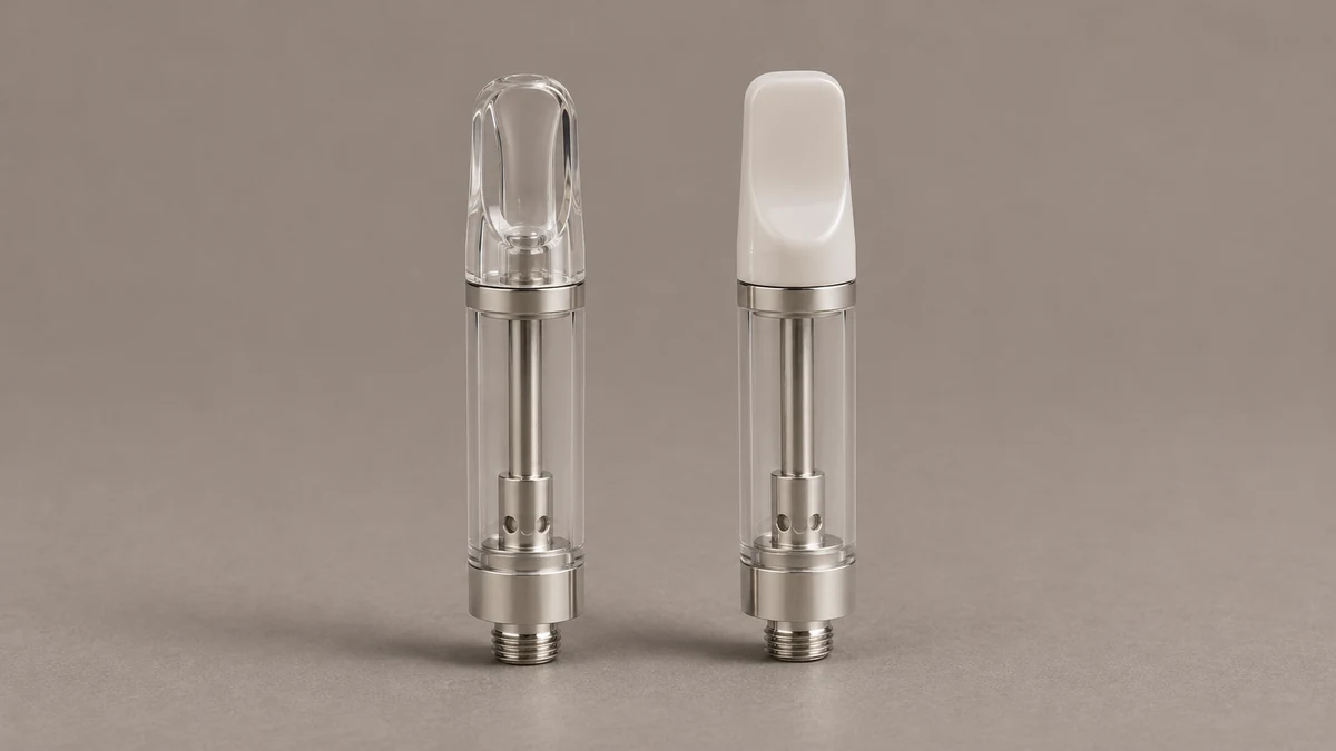
⚖️ 3. Two Hypothetical Samples, One Exterior
Consider two hypothetical, empty cartridge samples — Sample A and Sample B — that share the same outer shell, the same mouthpiece shape, and the same visible seam position, differing only in how the mouthpiece actually attaches to the tank.
The manufacturer’s TH2-SE specification lists snap-fit and screw-on mouthpieces for some capacities and specifies snap-fit for another. That illustrates why a closure description needs to name the configuration it covers. It does not establish that the versions share the same exterior or that a part from one can be fitted to another.
In hypothetical Sample A, the section view shows a feature on the mouthpiece that engages a matching retaining lip. The label points to the hidden interface rather than to the visible edge around the cap.
In hypothetical Sample B, the section view shows a threaded interface under a similar-looking cap. Name the closure as shown in the drawing. The example describes how it is built and does not establish that the part is intended to come apart in service.
🧱 3.2 Seam Placement When the Internal Assembly Differs
Even with different attachment methods, Sample A and Sample B could show the same seam line on their exteriors, because the seam marks where the mouthpiece meets the tank visually, not how it is held there mechanically.
A drawing set addressing both samples would need a seam callout noting that the seam’s location is consistent across versions while the attachment detail behind it is not, a distinction that matters for anyone sourcing or specifying hardware from a photo rather than a drawing.
🗂️ 4. Turning Reader Questions Into Drawing Requirements
Three reader discussions prompted the questions below. They describe different cartridge reports and are useful for deciding what a drawing or support photograph should identify. They do not establish the cause of the reported condition or the hardware design of a CBD oil pen.
One reader reported a sticky exterior and noticed that a second cartridge looked different. Replies proposed possible causes, which were not verified. A support photo can name the visible location without turning that observation into a conclusion about the origin.
Another reader posted a picture after dropping a cartridge and seeing damage near the top. The question is easier to describe if the picture identifies where the mouthpiece ends and where the body begins.
A third reader reported a crack down the side without visible leakage. The replies disagreed on what to infer. Record the crack location and leave the condition of the internal seal unresolved when the image cannot show it.
💧 4.1 Surface Residue and the Limits of a Single Photo
In the residue example, a single exterior photo could show where sticky material sits on a cartridge — near the mouthpiece seam, lower on the tank body, or elsewhere — but it cannot establish whether that location corresponds to a seal, a seam, or neither, because none of those were specified in the original post.
⚠️ 4.2 Visible Damage Versus an Intact-Looking Cartridge
If a seam and a mark both appear near the mouthpiece, use the drawing to label them separately. A clear view can establish where the visible damage sits. It cannot determine whether hidden components were affected.
A support-intake photo taken for this purpose would ideally capture the mouthpiece, the seam, and the tank body as separate, clearly lit regions, so damage can be located relative to each rather than described only as damage at the top.
📋 5. What an OEM Drawing Set Should Specify Before Tooling
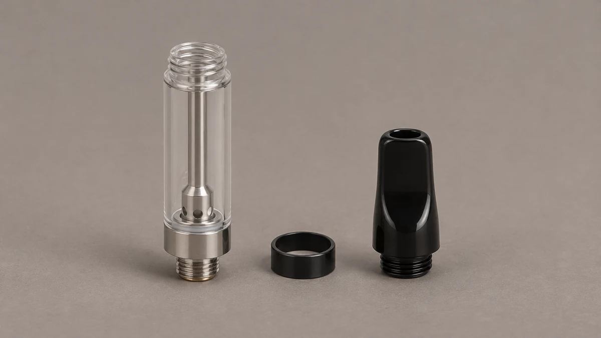
For an OEM review, use the section drawing to identify the closure and the assembly view to label the visible landmarks. The oil pen design overview discusses broader heater considerations. Keep the closure callouts in the drawing for the configuration being reviewed.
A complete drawing package for an oil cartridge’s closure would include, at minimum, a cross-section showing the mouthpiece seat and seal location relative to the tank, a callout distinguishing the seam’s location from its mechanical function, and an explicit attachment-type specification that is not left to be inferred from an exterior photo or a marketing description.
🏭 5.1 Platform Scope and What a Drawing Set Does Not Cover
A platform description provides context for the design family. In the closure drawing, use the revision to identify exactly which mouthpiece and seal belong together. The refillable cartridge overview covers another distinction: refill status must be established separately from the shape of the top.
📖 5.2 Documentation Gaps Left by Category-Level Comparisons
Category-level comparisons that distinguish hardware families are useful for understanding what kind of device a given sample belongs to, but they generally stop short of addressing closure drawings or photo documentation for seam and seal location within a single category.
The Vaping360 hardware comparison addresses the differences between device families. A closure diagram answers a narrower question about the assembly inside one particular cartridge.
📷 6. Ask for the Views That Locate the Seam
When a reader sends a single close-up of an empty cartridge, it may show a dark line without identifying where the line sits. Ask for an assembled side view that includes both ends, then a second view from a different angle at the same distance. The first photo puts the line in context. The second helps separate a reflection from a mark visible on the hardware. Include the carton label or revision identifier separately so it does not obscure the part. If the piece appears damaged, the photo is a record for support and does not establish that it remains fit for use.
📍 6.1 Describe Location Before Assigning Cause
Consider two support notes for the same sample. One reads “the seal failed.” The other reads “a narrow line appears just below the mouthpiece rim on one side.” The second statement describes what the photo supports. Pair it with a full view and the component drawing. If the drawing places the seal lower inside the assembly, the visible line may name an entirely different feature. Keep the observation and the possible causes separate until a manufacturer has examined the part or supplied the applicable drawing.
🖼️ 6.2 Keep the Reference Photo Separate From the Reported Unit
A support page can use a clean, empty production reference to show what a particular seam looks like. Give that image a caption with the revision and the angle. A reader’s photograph serves a different purpose: it shows one unit under its own lighting and viewing conditions. Comparing the two is easier when both use the same orientation and call the mouthpiece end by the same name. If the reference photo is a rendering or an older prototype, identify it as such.
🗂️ 7. Handoff Notes for Two Similar-Looking Closures
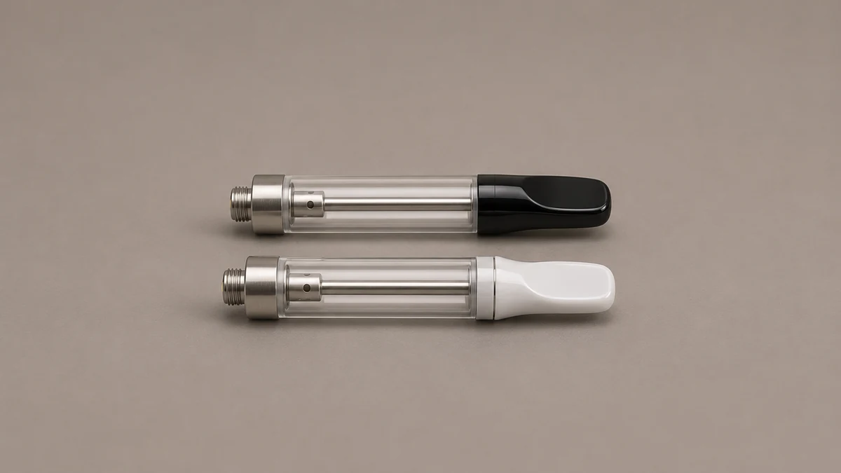
If a custom housing shares its outside shape with an earlier version, keep the relevant closure drawing close to the product image in the support library. Suppose Version A shows a threaded top while Version B shows a snap-fit top inside an exterior cap that looks nearly identical. Store the drawings under distinct revision identifiers. The outward resemblance is useful for identifying the product family, but the revision is what allows a reader to select the appropriate part description.
The existing hardware platforms overview describes the difference between starting from a reference product and changing a structure. A closure drawing belongs in that discussion because it shows which parts change together. Keep the document tied to the cartridge or housing it describes and make clear whether a detail is part of the released design or a proposed variation. A note about an unresolved detail is more useful than a generic claim that an entire family uses the same closure.
Three documents make the final reference useful: the assembled photograph, a section view through the mouthpiece and seal, and a parts list that identifies the revision. Together they let a support team name the visible joint and explain what the image cannot show. When a photo fails to locate a mark or a drawing omits the closure, ask for the missing view. The hardware description remains accurate even before the cause of a particular report is known.
🧾 7.1 Record What Changed Between Two Drawings
For a hypothetical revision review, set the section drawings side by side and align them at the top edge of the tube. Mark the edge of the mouthpiece and the location of the internal seat in each drawing. One revision may move the seat while leaving the visible seam where it was. In another, the seam may move because the collar shape changed, even though the internal arrangement is unchanged. The two notes should identify different changes. This is particularly helpful when a product photograph is being carried forward from an earlier revision and still looks reasonable at first glance.
A change note can also record which supporting files need to be updated. A new exterior cap may call for a new photo. A revised internal seat may call for an updated section drawing even when the photo stays useful. If the part number changes, update the parts list and the caption in the support reference together. A person who sees the older image later should be able to tell whether the image is still valid for identifying the visible seam, and which drawing they need to interpret the hidden closure.