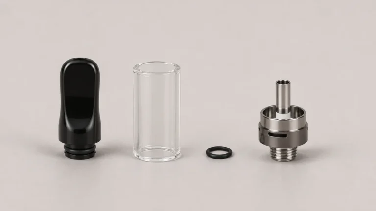
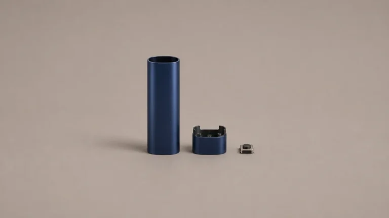
In a custom vape pen, a button can be easy to see in a rendering and hard to find on the assembled shell. Look at the geometry as someone would encounter it: the orientation of the body, the place where the fingers settle and the clearance around the control. An empty mockup gives the designer a way to compare those features separately.
🧭 1. How the Shell Establishes Front and Back
Set an empty, unpowered pen-style enclosure on a table and look at it before picking it up. A flat face, the position of a cap seam or the outline of an indicator window might suggest which side is the front. If those clues point in different directions, the physical layout is worth examining before the next prototype.
Before that person touches anything, the questions they ask are physical rather than electronic: which end is meant to face up, is there a side intended to be read as a front, and does the shape itself suggest an answer before any button is pressed.
With no screen lit and no indicator glowing, the only available orientation cues are tactile and visual — a seam where two sections meet, a flat face set against a rounded one, a printed icon, or a slight step in the outer profile.
🧭 1.1 Reading the Body Without a Lit Display
A listing for AOVAPE’s 650mAh digital display vape pen battery documents a design where a single button is paired with a display positioned near the base of the body, but that documentation only tells a reader where the display sits on paper — on an unpowered, empty version of a similarly shaped body, nothing would actually glow, so the same positional fact would have to be confirmed by feel or by a printed marking rather than by light.
That distinction matters for first-look orientation: a hypothetical mockup with a small clear window near the base and a single raised button on the opposite face gives a person two candidate cues to reconcile — window location and button location — and only physical inspection, not assumption, tells them whether those two features are meant to be read together or independently.
📐 1.2 What a Line Drawing Establishes and What It Leaves Open
A hypothetical diagram showing a plain cylindrical silhouette with a dashed circle marking a button position communicates exactly one thing — where, in relative terms, a control sits along the body’s length and around its circumference — and nothing beyond that.
If two such diagrams are placed side by side, identical except for the button’s height relative to the base, the comparison only proves that two different placements are drawable; it does not establish how either would feel to a thumb, how far either would protrude, or whether either placement would be easy to find without looking, since none of that is information a flat diagram can carry on its own.
✋ 2. Hand Indexing and Grip Variation
Hand indexing describes where the fingers settle when someone picks up the shell. The location depends on the person and the shape they encounter. It is useful to observe where the thumb lands relative to a candidate button position on an inert sample. That tells you something about the particular grip you observed without assuming that every hand will settle in the same place.
🖐️ 2.1 Three Hypothetical Grips on One Mockup
Take an empty mockup and imagine three ways of holding it, purely as illustration and without any claim that one is preferable: a pinch grip near the base, with thumb and first two fingers close to the bottom end, places the index finger pad near whatever sits low on the body; a closed-fist wrap, with the whole hand encircling the body and only the thumb left free to move, puts a control near the top within easy thumb reach while a control near the base sits closer to the heel of the palm than to any fingertip; and a two-finger bridge grip, holding near the top end with the body resting diagonally across the palm, leaves a control near the base out of contact with any finger at all.
None of these three outcomes says anything about which grip a given person would choose or how comfortable any of them would be — they only illustrate that the same fixed control location produces three different proximity outcomes depending on how the hand happens to be arranged around the body at that moment.
🔄 2.2 Left- and Right-Hand Mirror Differences
If a hypothetical control sits on only one flat face of the body rather than wrapping around the full circumference, a right hand using a pinch grip and a left hand mirroring that same pinch grip rotate the body in opposite directions to bring that face into reach, which means the face a person ends up looking at during a first-look inspection can differ by which hand did the holding, not by anything printed or molded differently on the hardware itself.
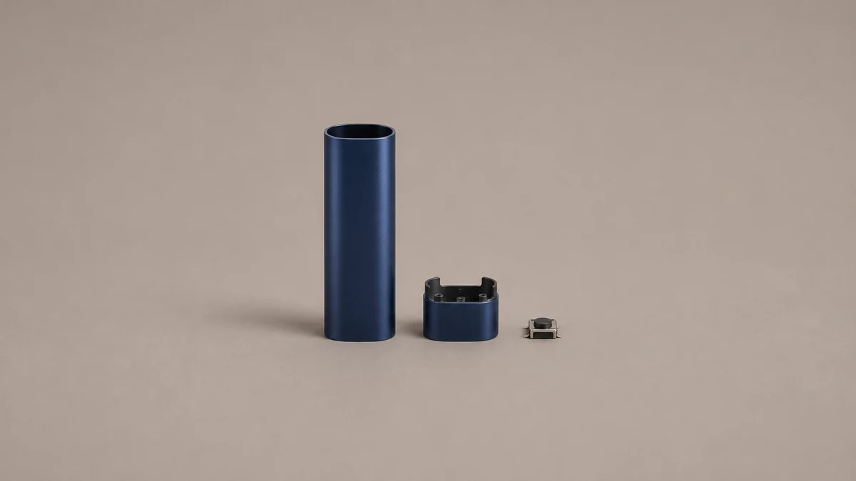
AOVAPE’s two-part 510 device documents a shell and lower power section that separate. It illustrates why a drawing should label the surface that stays visible when the parts are assembled. On a hypothetical sample with a control near that joint, the two assembled viewing angles may reveal different parts of the same button edge.
🔘 3. Location Versus Protrusion: Two Separate Design Questions
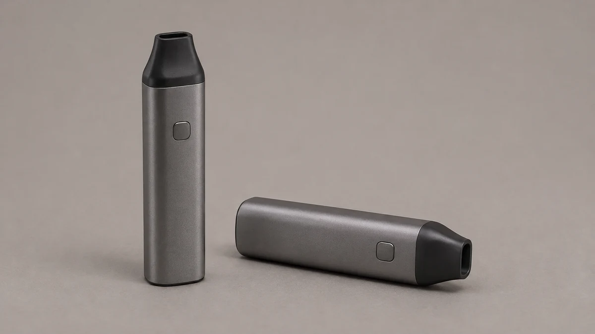
It helps to treat “where a control sits” and “how far it stands out from the surrounding surface” as two unrelated questions, because a control can occupy any candidate location while sitting flush, recessed, or raised, and changing one of those two properties says nothing about the other.
A simple way to see this is to imagine a 2×2 arrangement of hypothetical mockups: two share the same location near the base but differ in protrusion, and two share the same raised protrusion but sit at different locations along the body — four distinct outcomes built from only two variables, none of them implying the others exist in any real product.
📍 3.1 Location Along and Around the Body
A hypothetical diagram marking four candidate positions on a plain cylinder — near the top end, near the base, centered on a front face, and offset onto a side face — is useful only for showing how many distinct positions are possible in principle before protrusion is even considered; the four marks are not meant to represent four real configurations, just four points on a map of where a location question could land.
⬆️ 3.2 Flush, Recessed, or Raised Relative to the Shell Line
A control that sits flush with the surrounding shell may be identifiable only by a thin seam or an etched icon around its edge, while a raised version with a physical rim stands out enough to be found by touch alone, and a recessed version sits below the surrounding surface in a shallow well.
A hypothetical cross-section diagram showing all three protrusion heights at the identical location along the body makes the geometry of each option legible, but a cross-section only communicates shape — it says nothing about how easily a finger sliding along the shell would notice the difference, which is a separate, untested question the diagram does not answer.
🧩 4. Removable Shells, Caps, and the Controls They Can Cover
🔓 4.1 Distinguishing a Removable Mouthpiece from the Outer Shell
One reader asked about a replacement after a mouthpiece shattered. That question is a reminder that people use familiar names for whichever part they can see. A mouthpiece can be a separate component, while a larger shell can define the visible side of the device. The part drawing should identify both if they meet near a control.
A cutaway of an empty housing can show whether a removable shell stops short of a button or surrounds it. Mark the seam on the assembled photo too. When those references match, it is easier to tell which piece is visible and which piece carries the control beneath it.
🎯 4.2 When a Cap or Shell Sits Directly Over a Control
In a hypothetical mockup, a removable shell section could be positioned so that, once installed, it physically covers a button on the base beneath it — meaning the control exists on the hardware but is not visible or reachable until the shell is removed, which changes what a first-look inspection can actually discover while the body is fully assembled.
An exploded hypothetical diagram showing the shell lifted away from the base, next to a second view with the shell closed over the same base, illustrates this directly: the closed view shows a continuous, apparently control-free surface, and only the exploded view reveals that a button was there all along, underscoring that an inert mockup’s outward appearance in its assembled state does not guarantee a complete inventory of its controls.
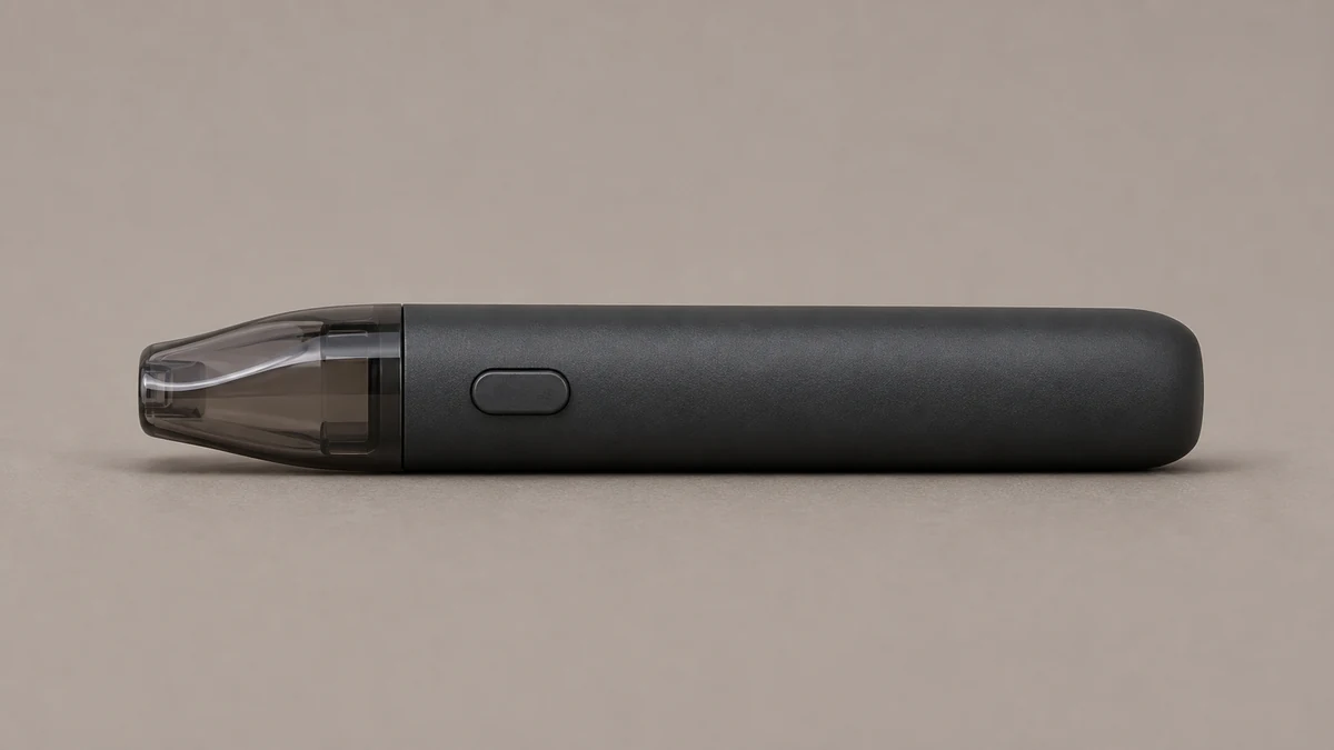
👀 5. Comparing Two Similar-Looking Pen Bodies
🧪 5.1 Same Silhouette, Different Control Count
Readers have posted pictures of similar-looking pen bodies with different details at the connector. A side-by-side silhouette would not have answered their question. For a control layout, the same issue arises when a rendering hides a button behind the visible face or shows only the face without the adjoining seam.
A Vaping360 review of the PCKT Vrtcl documents how controls are arranged on that one specific, named device, and that documentation is useful precisely because it is tied to that device — findings written about one named, documented body do not transfer to a different, undocumented mockup just because the two happen to look similar from across a bench.
📄 5.2 Why Documentation Matters When Only One Control Is Present
One reader described a single control with several light responses and asked how to interpret one of them. That question exposes a limit of the physical comparison: a mockup can show where the button is and how it meets the shell. The intended control behavior belongs in separate model documentation.
The custom vape pen battery specification guide covers the broader design brief. Keep the physical layout notes specific enough that another person can see the same button and seam on the drawing. A separate record can describe the electronics once those requirements have been confirmed.
📏 6. Compare Layouts With the Same Empty Mockup
A physical layout comparison is easier to interpret when only one feature changes at a time. For the first pass, use two empty samples with the same length, cross-section and surface finish. Move the button position on the second sample, while keeping its shape and height the same. A reviewer can then describe whether the control sits under a finger, near the edge of a grip or behind the hand. If the samples also differ in width or texture, it becomes harder to tell which difference changed where the hand landed.
🖐️ 6.1 Record Where the Hand Lands Before Pointing Out the Button
Start with the shell in a neutral orientation on the table. Ask a reviewer to pick it up as an object and describe what they notice. When someone points out the button in advance, they introduce an orientation cue that will be missing when someone first sees the device. Record whether the reviewer oriented the shell by its flat face, by the cap seam or by another feature. A second reviewer may use a different clue. Those are observations about the samples in hand and can inform the next comparison without predicting how everyone will hold the finished product.
When a button sits close to a seam, reviewers may identify the seam first and then follow it around the housing. That can help them find the control on one sample and lead them away from it on another. If this happens, place both samples in the same orientation and take photographs that show the seam and button together. Keep the photos alongside the dimensions. A note such as “control is on the flat face next to the shell joint” is easier to check than “control is easy to find.”
📐 6.2 Check the Clearance With the Shell Installed
An exploded drawing can expose the button and its retaining structure, but readers also need to see what the assembled shell reveals. In a hypothetical two-piece design, an outer rim might sit a little higher than the button surface. The drawing can show whether the button is recessed relative to the rim and whether the shell edge comes close enough to obscure part of it. Show that relationship on a side view and a section. If a prototype is missing the final finish or trim, note that in the comparison so its visible clearance is treated as provisional.
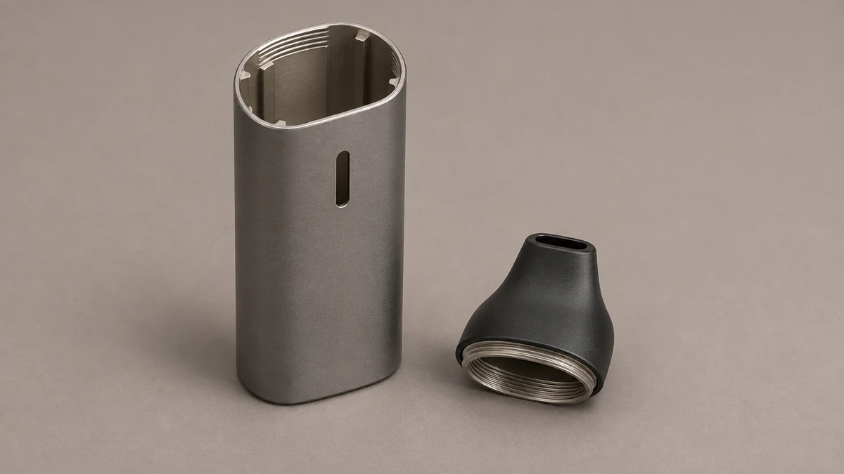
🗂️ 7. Hand Off the Control Drawing With an Assembled View
The existing vape hardware platforms page distinguishes appearance changes from changes to the enclosure or structure. For this kind of layout review, keep those decisions separate in the drawing. A change to the button cap color may leave its location and projection intact. A change to the shell profile may alter the geometry around it. When a change affects two parts, put both revision identifiers on the assembled view so reviewers can tell which combination they saw.
Use consistent names for the front, side and base across the photos, section views and notes. If a housing has no obvious front, define the control face once and label it in every drawing that depends on orientation. A final comparison should let another reviewer locate the control on the assembled shell, see how far it projects and understand which surfaces surround it. Leave any finding about comfort or preference attached to the specific sample and review conditions that produced it.