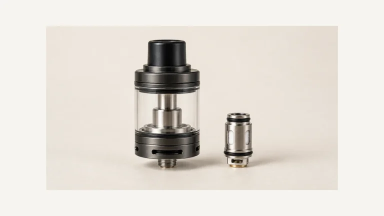
A 510 thread tank can be maintained as several parts: the liquid reservoir, a replaceable coil head where the design provides one, the mouthpiece and the seals joining the assembly. That is the practical difference to understand when moving from a sealed cartridge to a serviceable tank. An old coil does not necessarily mean the whole tank needs replacing, and cleaning the reservoir does not necessarily restore the coil. The tank’s bottom connector lets it attach to a compatible power unit; it does not tell you how the internal parts come apart or which replacements they accept.
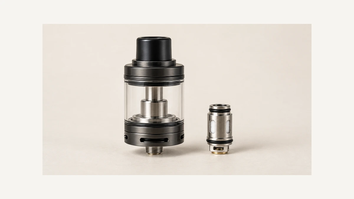
🧩 1. What a 510 Thread Tank Actually Is
The liquid-tank examples shown here are not wax chambers, dry-herb ovens or oil cartridges. Their shared connector terminology does not make those hardware categories interchangeable.
Here, tank means a serviceable refillable assembly intended to use premade replacement coil heads. Other tank formats exist, including rebuildable designs, but those have different maintenance instructions. The 510 thread tank described by a search result may look familiar while having a different top closure, reservoir wall or coil attachment. Start with the actual layout. Identify which section holds liquid, which part carries the air passage, and which parts the maker intends the owner to remove. A screw connection at the bottom does not standardize all those details.
🔎 1.1 Why a Screw Fit Alone Doesn’t Make a Tank
A sealed oil cartridge can use a similar bottom connector while keeping its heating assembly inside a cartridge intended to be replaced as a unit. A serviceable tank instead provides access to specified replaceable parts. There are exceptions on both sides, so refillability and coil replaceability should be checked separately. A removable mouthpiece alone does not establish that the heater is user-serviceable. The box-mod and cartridge guide explains why attaching an oil cartridge to a larger body also needs the right electrical support. The reverse assumption is equally unhelpful: a small cartridge battery is not automatically an appropriate power unit for a tank.
🔎 2. Reservoir Space Versus Center Chimney
A familiar cylindrical layout places the reservoir around a central chimney. The outer space holds liquid, while the central passage carries aerosol toward the mouthpiece. The coil head includes a material-feed arrangement and an air passage, connecting the reservoir’s function with the heating area. Treat those spaces as distinct even when both are visible through the glass. The central opening is not a second fill port simply because it is easy to see from above. The actual tank instructions identify the intended fill opening and the path that should remain clear.
🔎 2.1 Why Mixing Up the Two Spaces Leads to Wrong Guesses
This distinction helps describe a wet or messy tank without guessing at the cause. Liquid in the visible reservoir is different from liquid appearing at a mouthpiece or outer air opening. An empty-looking reservoir also does not establish that every internal surface is clean and dry. Inspect the accessible parts with the device off and cooled, according to its care instructions. Avoid assigning a wet passage to a worn seal, overfilling or a cracked chimney without examining the assembly. Those are different possible conditions, and each needs its own evidence on the actual part.
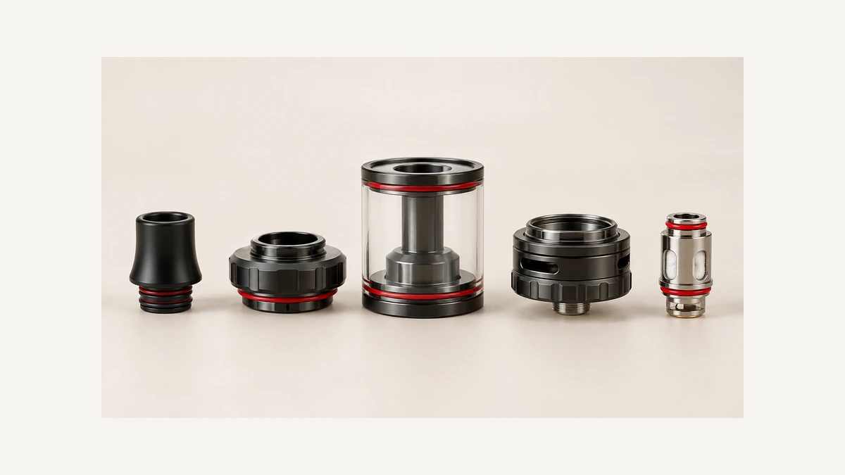
🔧 3. Top Cap, Fill Opening and Air Passage
The top closure can be threaded, hinged, sliding or otherwise retained, depending on the tank. It may cover the fill opening and support a removable mouthpiece, but those functions need not share one removable component. A fill gasket can remain attached under a sliding cap, for example, while the mouthpiece has a separate socket. Notice which part moves and which remains fixed. A seam near the top is not necessarily a place to unscrew, and removing a mouthpiece does not necessarily expose the intended fill area. Follow the design’s own opening method rather than forcing a familiar motion onto a different closure.
🔎 3.1 Fill Port Placement and the Leak-Free Tank Question
In an owner thread asking for a tank that does not leak, replies name several preferred devices and describe different experiences. They do not provide a controlled comparison or establish a guarantee for an airflow location. The practical question is how the particular tank contains liquid when its closure, coil and seals are correctly assembled. A damaged reservoir wall and an incorrectly seated closure need attention even on a design someone else calls leak-free. Keep any visible liquid away from the power unit and follow the actual tank’s troubleshooting guidance.
🔄 4. Threaded Coils Versus Press-Fit Coils
A threaded coil head and a press-fit coil head use different attachment methods. One engages its intended threaded interface; the other seats into a specified opening without that threaded engagement. Neither is automatically interchangeable with a similarly shaped head. Removal direction, access and whether the tank must be emptied depend on the assembly. Some designs include features intended to contain liquid during a coil change; others do not. Do not assume a coil sits in the same socket or can be removed with the tank in the same position just because the bottom connector is 510.
🔎 4.1 Replacing the Coil Versus Replacing the Whole Tank
Aspire’s Nautilus 3S component description distinguishes the top cap, coil, mouthpiece, outer tube and airflow ring, and describes a press-fit coil change system. It is a useful example of separately maintained parts, rather than a replacement guide for unrelated tanks. For a serviceable design, identify which component is actually damaged before replacing the complete assembly. A worn or faulty coil head, a damaged seal and a cracked reservoir wall are different parts issues. Taste or output alone cannot identify which one is responsible, and swapping a coil does not repair a cracked wall.
🏺 5. Glass, Seals and the Reservoir Wall
A removable glass section meets the adjacent parts through the tank’s intended seals. Other tanks can use different reservoir materials or a protected outer structure, so glass is not a universal construction rule. A seal’s shape and seating position matter: a ring that looks similar may still have a different cross-section or diameter. During permitted disassembly, keep the seals associated with their original locations. Look for cuts, displacement or visible damage rather than assuming every leak comes from an old coil. Tightening an assembly harder cannot restore a missing seal or a chipped contact edge.
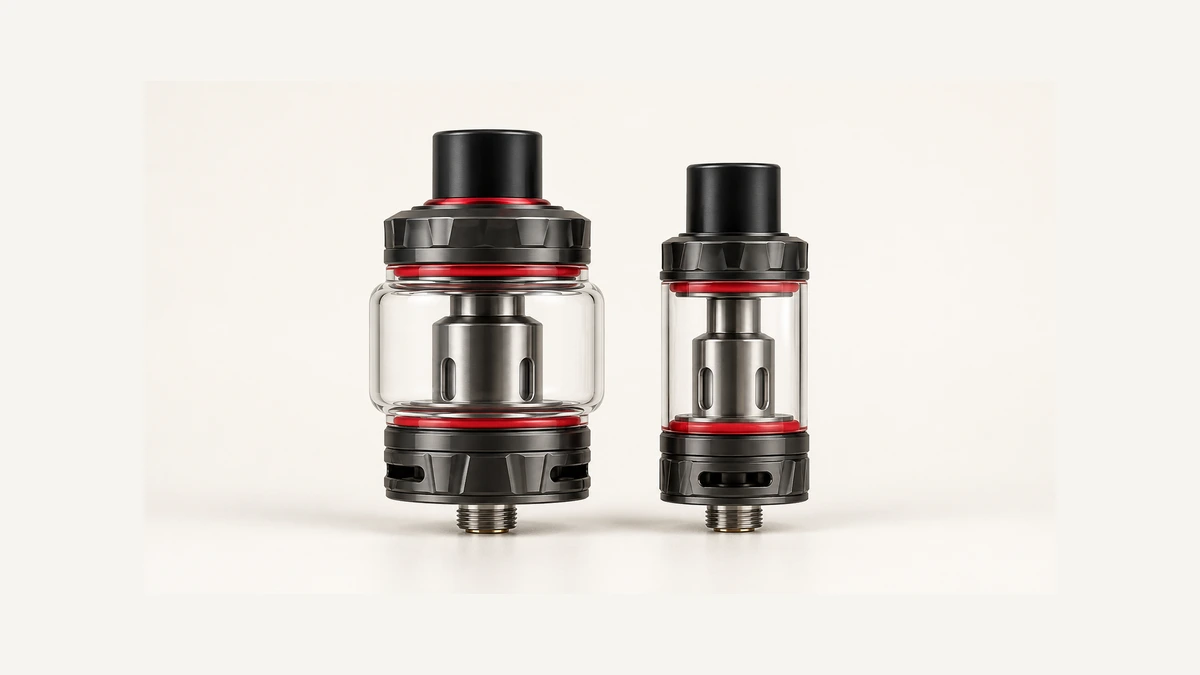
🔎 5.1 Straight Glass Versus Bulb Glass: Width and Storage
Straight and bulb-shaped reservoir walls change the tank’s outer outline. A bulb section may extend beyond the diameter of the base, which matters when placing the complete device in a case or narrow compartment. That width is different from the threaded connector’s size. Replacement glass must also match the intended seating surfaces and assembly height, rather than just looking close to the old part. Do not use a case that closes by pressing on the reservoir wall. The widest part of the tank, the height of the attached mouthpiece and the body’s shape together determine the space needed for storage.
⚡ 6. Coil Families and Electrical Support, Briefly
A coil family identifies a set of intended compatible parts, not simply a resistance range. Different heads within a family can have different resistances or permitted power ranges, and two unrelated families can contain the same resistance number. Physical dimensions, contacts and intended tank fit still matter. The power unit also needs to support the actual coil configuration. A coil being low resistance does not establish that it belongs to a particular tank, and a tank accepting a coil physically does not establish that every battery can drive it appropriately.
🔎 6.1 Why a Compatibility Chart Exists
A manufacturer’s current coil-platform page lists compatible tank bodies by coil version and gives separate power guidance. Use the actual part’s compatibility information rather than treating a shared family name as permission for every configuration. The coil compatibility guide develops that relationship between the head, tank and power unit. For routine maintenance, keep the exact replacement identity with the tank. A spare part chosen only by appearance can make reassembly seem correct while leaving the wrong interface or electrical configuration in place.
🔌 7. Two Different Things Called “510”
The word 510 also appears in mouthpiece descriptions. A 510 bottom connector is the threaded electrical attachment to the power unit. A 510 drip tip describes a top mouthpiece fitting. The two names refer to different interfaces at opposite ends of the tank. A question about an 810 mouthpiece and a 510 mouthpiece therefore concerns the top socket, not the bottom attachment. Keep the actual socket and seal arrangement in view when identifying a replacement. A mouthpiece adapter does not change which power unit or coil the tank supports.
🔎 7.1 When an 810 Mouthpiece Gets Confused With the Base
A recent mouthpiece-fit discussion asks about using a narrower tip with a tank described as having an 810 fitting. The owner also encounters confusion over an accessory described as an adapter or base. That is a useful reason to identify the interface before considering a part: does it belong at the mouthpiece socket, the coil attachment or the bottom connector? An adapter needs compatibility with that exact location. A visually similar ring is not automatically a universal size converter. Once the top and bottom uses of 510 are separated, the replacement question becomes much clearer.
🧽 8. Cleaning Old Residue Versus Replacing a Worn Coil
Old residue and a coil that needs replacement are separate maintenance questions. A tank’s permitted cleaning procedure may clear its removable reservoir and mouthpiece parts, while a coil head containing wicking material has a different care or replacement requirement. Do not diagnose a stale or unexpected taste as a particular failure merely from the description. It may involve the material, the coil or residue in an accessible path. Persistent unexpected behavior calls for the device’s troubleshooting process, rather than repeatedly changing liquids or trying stronger cleaners on the heater.
🔎 8.1 What Actually Gets Cleaned
Innokin’s care guide separates cleaning of removable atomizer components from the coil and states that the battery or mod must not be immersed. That distinction is useful, but the permitted cleaner and disassembly method still belong to the particular tank. A ceramic-cartridge construction guide can have a different service arrangement from an openable reservoir. Cleaning permission for a detached tank section should not be transferred to a sealed cartridge or electrical housing. Follow the actual part instructions and dry the components completely before reassembly.
💧 9. Leakage Visible at the Base Versus Its Real Origin
Liquid around the base is a location to inspect, not a confirmed source of the leak. Check the accessible reservoir joints, intended coil seating and closure, and distinguish a small exterior film from a continuing escape of liquid. Do not tighten the tank into the power unit harder simply because the wet area is near the connector. That threaded attachment has a different purpose from the seals holding the reservoir together. If the tank continues to leak after the permitted checks, keep it detached from the electrical body and request guidance for the specific assembly.
🛠️ 10. Putting the Tank Back Together in Order
Reassemble in the tank maker’s sequence, which can differ substantially between designs. Keep removable seals, glass, coil and mouthpiece parts organized as they come apart. Confirm that the intended replacement head is seated correctly and that each seal returns to its own location. A closure that meets at an angle should not be forced down to make the exterior look finished. A good reassembly check names the parts that were actually inspected: reservoir wall intact, intended seals present, compatible coil fitted and removable sections dry. That is more useful than assuming a tank is ready because its bottom thread screws onto the body.
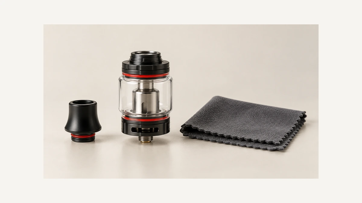
🧽 11. Keep the Cleaning Area and Spare Parts Organized
A tank can contain small removable pieces that are easy to overlook on a busy work surface. Use a clean area where a mouthpiece seal or coil ring remains visible, and separate the parts by their function. A removed coil head should not be confused with a cleaned reservoir component awaiting reassembly. Photographing the intended arrangement before disassembly can help with identification, while the actual instructions determine what is meant to come apart.
In an owner discussion about an old tank, the question was whether the connector and residue-covered assembly could simply be soaked. Replies offered conflicting methods. The useful distinction is between cleaning the accessible part and immersing everything together. Follow the permitted care for each material and keep the electrical body separate. If a stubborn deposit remains, seek tank-specific advice instead of transferring a solvent suggestion from an unrelated assembly.