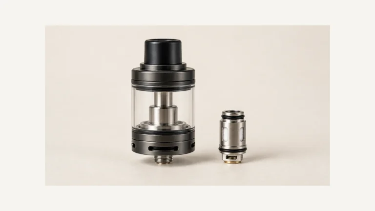
Opening an airflow control makes more of the inlet available, but it does not widen every passage inside the device. That is why a fully open tank can still feel tight, and why two different coils can feel different at the same ring position. Vape airflow is the whole route from the outside opening to the mouthpiece. The visible slider or ring adjusts one part of that route; the rest depends on the chamber, internal passages and attached mouthpiece. When a draw feels wrong, first separate a preference for a different restriction from a change in the way the existing device behaves.
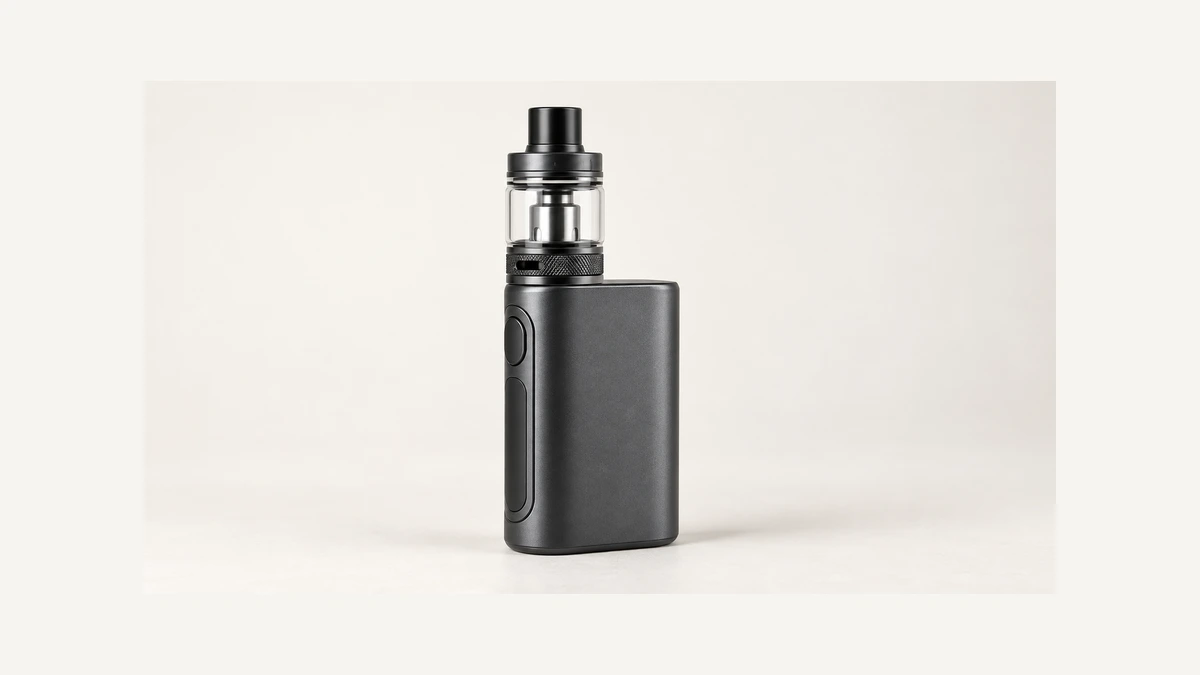
🌬️ 1. Vape Airflow Explained Along the Whole Path
🔎 1.1 Inlet Size vs. Internal Path
On an adjustable design, the control exposes or covers part of an intended air opening. It may be a rotating ring around a tank or a slider on a compact body. A fixed inlet is different: its opening is part of the construction, with no user-operated adjustment. From there, air follows the device’s internal route toward the heating area and mouthpiece. The exact path varies, so a familiar outer shape should not be treated as a diagram of the interior. Power controls change an electrical setting; an airflow control changes a passage. Raising power cannot remove a physical obstruction. The atomizer guide explains how the heating assembly fits into that larger system.
🔎 1.2 Draw Resistance Is Not One Dial
The opening you can see is only one restriction along the route. Internal channel dimensions, a removable filter where one is fitted, and the mouthpiece bore can all affect how easily air passes. A mouthpiece with a narrow passage remains narrow when the inlet ring opens.
Likewise, changing a coil head may change a section of the airpath even though the tank’s outside ring stays in the same position. Do not infer that a coil’s resistance number describes its airway diameter or that denser wicking must sit directly in the air stream. Electrical resistance and physical flow restriction are different properties. Describing both with the word resistance can make a straightforward hardware question sound more confusing than it is.
🎛️ 2. Where the Adjustment Actually Lives on the Device
🔎 2.1 Rings, Sliders, and Fixed Inlets
Innokin’s general support FAQ, published November 1, 2021, describes ring-based and slider-based airflow controls and also identifies fixed-airflow designs. For its adjustable systems, exposing a larger opening or more inlet holes makes more airflow available. It notes that a ring may be near the base or top of the tank. This is a useful anatomical example; it is not a universal direction-of-turn instruction or a preferred setting for every device.
🔎 2.2 Fixed-Airflow Devices Get Labeled Differently
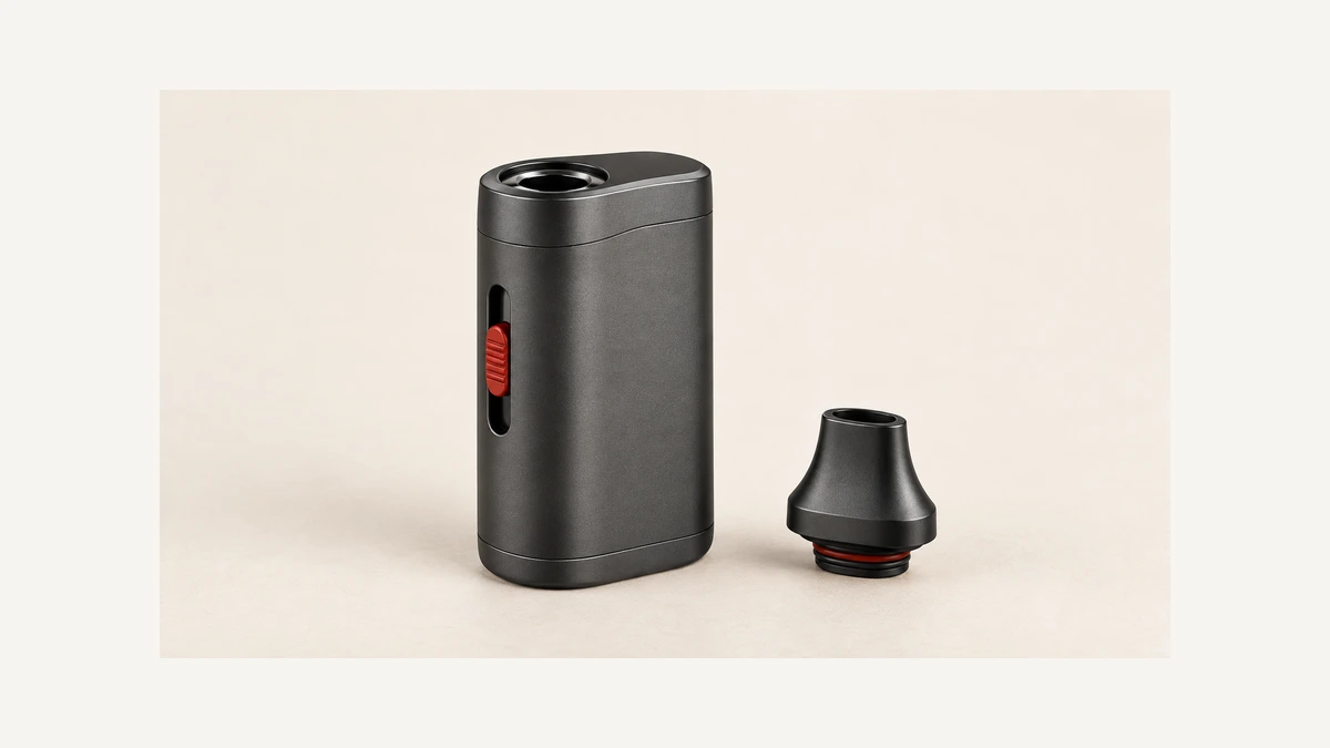
A small opening in the body is not necessarily an air inlet. Compact devices can place an attachment eyelet, charging port and control close together. One manufacturer’s manual labels its airflow toggle, lanyard hole and USB port separately in the component view. Check the actual drawing for your device before identifying an opening by appearance. On a genuinely fixed-airflow design there may be nothing to turn, and a decorative seam is not an adjustment ring. The absence of a ring also does not prove that a device is fixed-airflow; it might use another intended control elsewhere on the body.
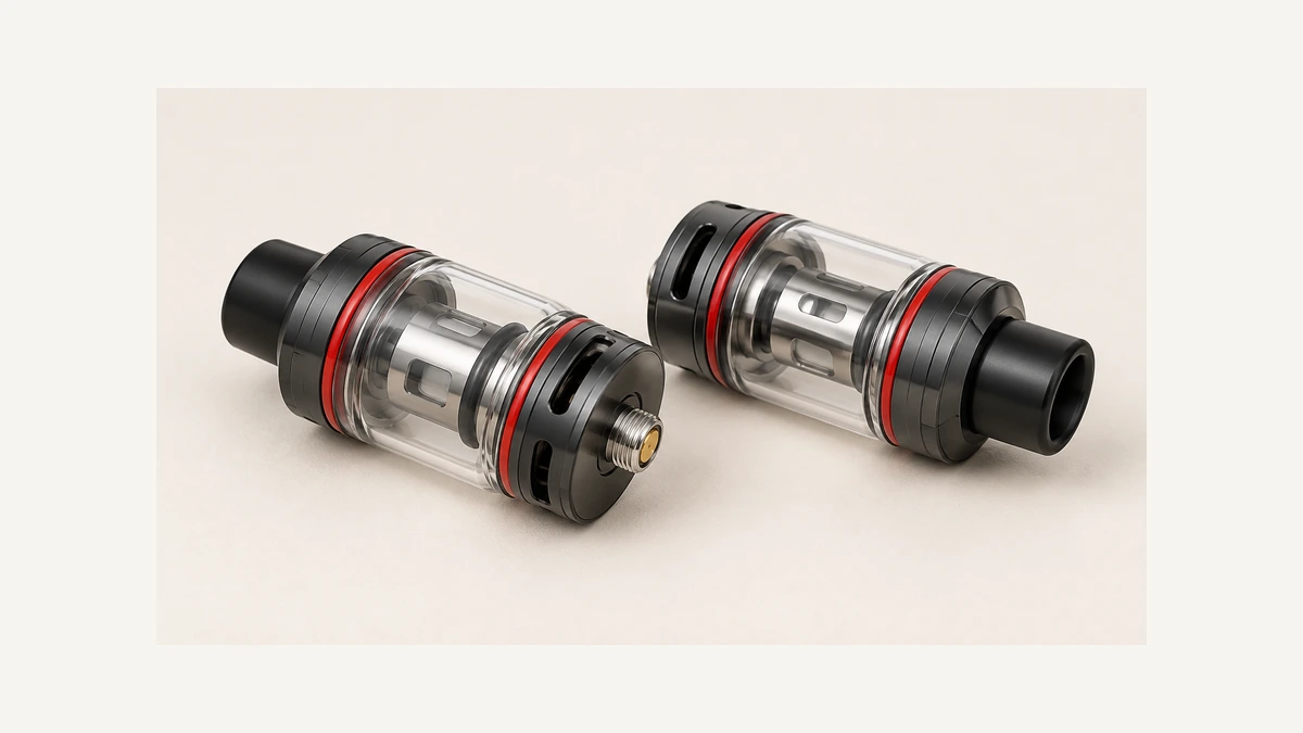
🔎 3. Why a Fully Open Ring Can Still Feel Tight
🔎 3.1 The Coil Channel and Mouthpiece Bore Are Bottlenecks Too
A fully open control describes the maximum opening at that control, not a promise of an unrestricted draw. Air still has to pass through the downstream route. A narrow internal channel or mouthpiece can limit the overall flow even when the outer inlet is exposed. That distinction is especially useful when comparing two devices whose rings both say open but whose internal layouts differ. The drip tip guide covers the removable mouthpiece’s fit and bore. A mouthpiece change also needs the intended compatible part: a wider-looking tip is not necessarily interchangeable, and changing a top component cannot alter a narrow section farther inside the tank.
🔎 3.2 Fingers and Holders Can Block the Inlet Without You Noticing
An external holder can cover an inlet without changing the control’s position. So can fingers wrapped around an opening near the base. Inspect the actual alignment of the holder, sleeve and exposed slots with the device off. A ring can appear fully open while an accessory sits directly over the available holes. This is a position question, separate from internal buildup or a damaged control. If the carrying accessory obstructs an inlet, remove it or use the intended compatible arrangement rather than cutting new holes in the device. Check that a slider can move through its designed range without the holder pressing on it.
🔎 4.1 Preference and Physical Change Are Different Questions
In an owner question about control settings, the reader asked whether one position applies across different materials. The visible replies do not establish a setting or a tested result. The informational distinction is that a preference is different from an observed change in the same hardware. This article does not recommend a position or describe ways to change taste, sensation or delivery. A ring angle is not a measurement of the complete internal passage.
A more precise hardware description names the control and the current component configuration. An adjustment ring may expose holes while a slider moves across a slot. Their positions do not form one shared scale. A fixed inlet has no corresponding user adjustment, even if an exterior seam resembles the ring on another product. Keep the component drawing with the description rather than interpreting an appearance as permission to modify an opening.
🔎 4.2 Same Ring Position, Different Coil, Different Draw
Older owner discussions also ask why an open ring still feels tight after the internal assembly changes. In one such thread, commenters distinguished the outer inlet from the internal deck. That is a reader question, not a controlled measurement or a recommendation to alter a coil. The observation to keep is whether the restriction changed with an intended compatible part, with the control position, or without either changing. Those are different comparisons. Avoid modifying a heater or packing foreign material into a fixed inlet to imitate another device’s draw. The intended adjustment range belongs to the whole system, and a visual resemblance between two assemblies does not make their internal passages identical.
💧 5. Reading Leaks, Whistles, and Gurgles
🔎 5.1 Liquid Visible at the Inlet vs. Liquid at Its Origin
Liquid appearing around an inlet identifies where it became visible, rather than proving where it escaped containment. Inspect the accessible reservoir joints, fill closure and intended coil seating according to the tank’s instructions. An exterior film can also be different from a continuing leak that returns after wiping. Keep those observations separate when requesting support. Moving the airflow ring may change the visible opening without repairing a damaged seal or incorrectly seated part. The location of the control at the top or bottom is therefore not, by itself, evidence that a device cannot leak. A control described as airflow adjustment still needs to be distinguished from a liquid-flow valve where a design has one.
🔎 5.2 A Whistle and a Gurgle Mean Different Things
Whistling and gurgling are different descriptions, but neither sound is a complete diagnosis. A changed inlet position may change airflow noise, while liquid in an air passage can produce a wet or gurgling sound. Record whether the sound changes with the intended control, whether liquid is visible, and whether the mouthpiece or coil assembly has recently been changed. Do not assume every whistle is harmless or every gurgle comes from the same fault. If liquid reaches the mouthpiece or the device behaves unexpectedly, stop and follow its troubleshooting instructions. Sound alone cannot tell you the condition of a seal, the amount of internal residue or whether an electrical fault is present.
🧽 6. Sudden Restriction vs. Normal Designed Restriction
🔎 6.1 When Tightness Is Just the Design
A tight draw can be intentional. The useful comparison is with the actual device’s normal behavior and intended configuration, rather than with a different tank that feels more open. Labels describing a tight or open draw are not engineering dimensions and do not specify a universal passage size. A device sold for a tight draw may still have an adjustment range, and a more open system can still contain internal restrictions. If the draw has been consistent since the device was new, note that baseline. Consistency is an observation, not proof that every part is correctly fitted or that a preferred draw must be available within the control’s range.
🔎 6.2 When Tightness Shows Up Suddenly
A new restriction deserves a check of what changed. Look at the control position, outside openings, intended removable mouthpiece and seating of user-serviceable components. Residue or debris may obstruct an accessible passage, but a sudden change should not be assigned to buildup without inspection. The mouthpiece cleaning guide explains how to keep that task focused on the removable part. Clean with the device off and cooled, using its permitted method, and let components dry before reassembly. Do not probe into a coil or sealed body with a pin. If the accessible route is clear and the change persists, give support the specific symptom instead of repeatedly changing unrelated settings.
🧩 7. Auto-Draw Triggers Are Not Airflow Controls
On a draw-activated device, sensing a draw and adjusting the airpath serve different functions. The trigger activates the heating system; a ring or slider, where fitted, adjusts an intended opening. A device can have draw activation with fixed airflow or draw activation with adjustable airflow. Air passing through is not proof that the heater has activated, and a light or screen response does not prove that every passage is clear. Keep the symptoms distinct: a restrictive draw, an activation problem and an error indication call for different checks. Opening the ring is not a general repair for a device that does not register a draw.
A useful note for a recurring problem names the unchanged parts as well as the change: the same mouthpiece and intended coil are fitted, the holder is clear of the inlet, and the draw has become tighter at the same control position. That description gives the next inspection a starting point. Simply saying “the airflow is bad” mixes preference, obstruction and activation into one complaint.
🧭 8. Keep the Airflow Question Specific
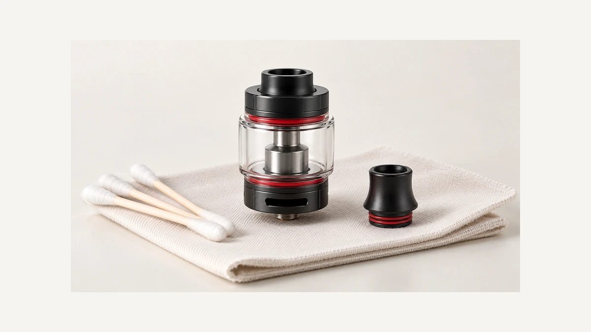
When inspecting an unfamiliar device, locate the inlet, the intended control and the removable mouthpiece before changing anything. A ring may have several holes, a long slot or discrete positions. A slider may expose an opening without displaying a number. Those layouts describe the available control rather than a shared scale across products. Half open on one ring is not a measurement that transfers directly to another.
A control that is difficult to move needs a mechanical check with the device off and cooled. Wipe accessible external residue using the permitted method, and avoid forcing the ring with tools. Some rings are removable for care; others are retained parts. A seam is not enough to tell you which. If a control is stuck or visibly damaged, use the maker’s instructions for that assembly instead of treating more force as an airflow adjustment.
For an ordinary preference question, keep the intended parts and their operating instructions in view. Airflow changes one part of the route. It does not change the coil family, create a new mouthpiece socket or add an adjustment to a fixed inlet. That is the useful limit to remember when a device’s most open position still has more restriction than you expected.