🧭 1. The Fit Question That Starts Every Build
Most confusion around a concentrate vaporizer with a bubbler starts before any vapor is produced. It starts at the joint. Someone has a loadable heating element — often called an atomizer, a coil, or a “nail” depending on the design — and a separate glass piece with a water chamber, and they’re trying to figure out whether the two parts will actually connect. That question shows up constantly in hardware discussions: people asking for a “510 concentrate attachment with water filtration” are really asking a threading and sizing question, not a performance question.
A 510 thread is an electrical and mechanical standard, not a size of glass joint. It tells you how the heating element screws into a battery or mod. It says nothing about whether that heating element’s output end will seat into a 14mm or 18mm glass joint, or whether that joint is male or female. This is where fit confusion actually lives: at the seam between an electrical threading standard and a glass joint standard, two systems that were never designed around each other and only work together because an adapter bridges them.
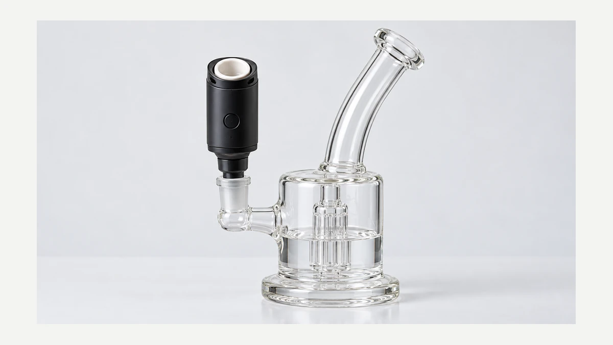
Once that seam is understood, the rest of the airpath makes more sense, because every other connection point in the device follows the same logic: a defined opening on one side, a defined opening on the other, and either a direct match or an adapter in between.
🧩 2. Mapping the Airpath From Heater to Mouthpiece
A concentrate vaporizer with a bubbler is really a chain of chambers, each with its own job. Vapor has to travel through all of them in sequence, and a problem at any single point — a loose adapter, an undersized inlet, a cracked downstream joint — changes the behavior of the whole chain, not just the part that’s damaged. Breaking the chain into its distinct zones makes it much easier to diagnose fit issues or airflow complaints without guessing.
📏 2.1. The Heater Zone
This is where the concentrate actually contacts a heated surface, whether that’s a coil, a ceramic element, or a quartz surface. Its output end is a fixed size and shape — almost always a male or female glass joint, or a 510-threaded housing that itself terminates in a glass joint through an adapter. Nothing about airflow happens here; this zone only produces vapor. Draw resistance and filtration are determined further downstream.
🌬️ 2.2. The Adapter and Inlet
The adapter is the single most misunderstood part in the whole airpath, and it’s the part that generates the most “will this fit” questions. Its job is to convert one joint size or gender to another so the heater’s output can seat into the water piece’s inlet. An inlet is simply the opening on the water chamber that receives vapor; depending on the design, that inlet may or may not extend down into the water itself.
Whether the inlet’s downstem reaches below the waterline matters more than most buyers realize. If the stem terminates above the water, the vapor largely bypasses the liquid and the bubbler is mostly cosmetic. If it terminates below the waterline, the vapor is forced through the liquid, producing the bubbling action people are referring to when they use that word in the first place.
⚖️ 2.3. The Water Chamber
This is the reservoir itself, and its only function is to hold a volume of liquid that the incoming vapor path is forced through before continuing upward. The chamber’s size, shape, and percolation design (simple open tube versus a disc or tree percolator) change how much surface area the vapor contacts as it passes through the liquid, but the basic principle is the same across designs: vapor enters below the surface, travels up through the liquid, and exits as bubbles release it toward the mouthpiece.
🧼 2.4. The Mouthpiece
The final zone is the exit point, where the user draws the vapor out after it has passed through the water. Some mouthpieces are fixed to the glass; others are removable for cleaning access. Either way, this is the point furthest from the heat source and closest to room temperature, which is part of why it’s also the zone most prone to condensation buildup over repeated sessions.
📏 3. Draw Resistance and Why Water Changes the Pull
A recurring theme in hardware discussions is wanting something “gentle on the throat,” and that phrasing usually points to draw resistance rather than temperature. Draw resistance is simply how much effort it takes to pull vapor through the entire airpath, and adding a water chamber changes that resistance in two directions at once.
On one hand, forcing vapor through liquid and then through open headspace before the mouthpiece tends to cool it slightly compared to a dry path of the same length, because the vapor transfers some heat to the water and surrounding glass. On the other hand, percolation features that increase surface contact — multiple slits, discs, trees — also increase the physical resistance the user has to pull against. More percolation generally means a smoother, denser pull but a harder draw; less percolation (or a simple open downstem) means an easier draw with less filtration contact.
| Airpath feature | Effect on draw resistance | Effect on vapor delivered |
|---|---|---|
| Open single-slit downstem | Low resistance, easy pull | Minimal cooling, minimal filtration contact |
| Multi-slit or disc percolator | Moderate to high resistance | More surface contact, more cooling |
| Tree or multi-arm percolator | Highest resistance | Maximum surface contact, strongest cooling effect |
| Deep water fill | Increases resistance regardless of percolator type | Longer vapor travel through liquid |
This matters for the “flower and concentrate vape for water filtration” question too, because a device built to handle both loose material and concentrate is really describing two different heater zones sharing one downstream airpath. The water chamber and mouthpiece don’t change based on what’s being heated; only the heater zone does. That’s why some hardware is sold as a chamber plus interchangeable heating attachments rather than as two separate complete devices.
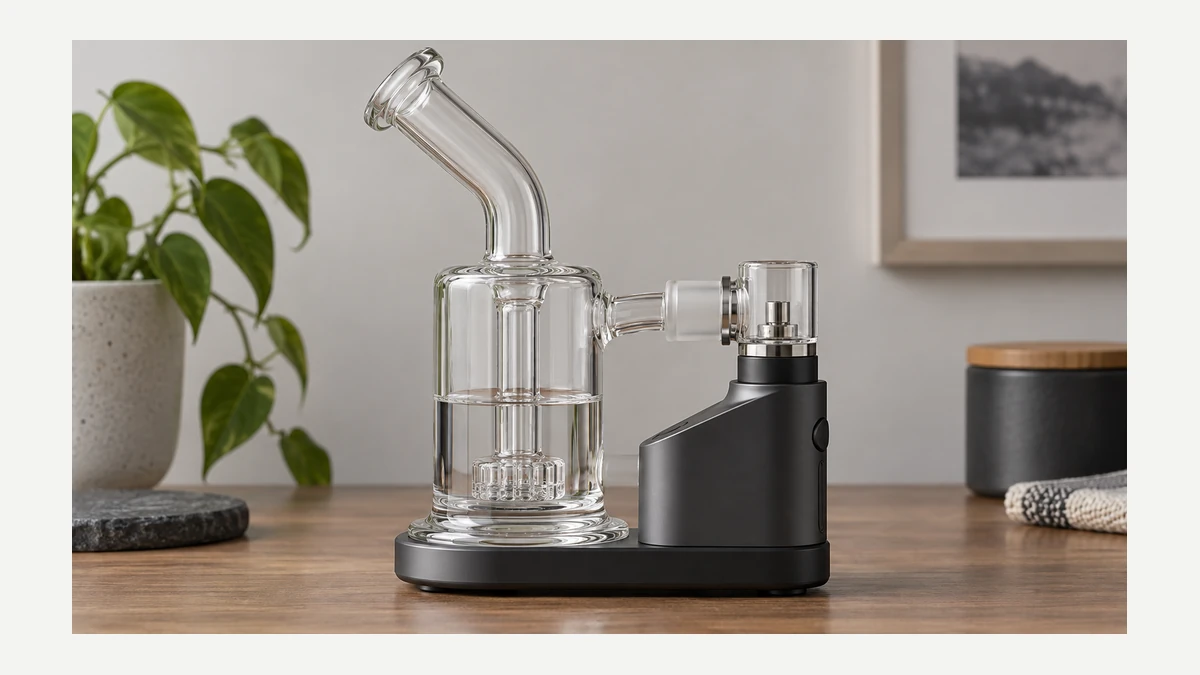
Fill level is worth separating out on its own, because it’s adjustable in a way the hardware itself isn’t. Too little water and the downstem isn’t submerged enough to force vapor through it, reducing both filtration and cooling. Too much water and the user risks liquid splashing up through the mouthpiece during a forceful draw. Most chambers have a visible fill line or a downstem length that implies the correct level; when there’s no clear marking, the simplest check is confirming the slits or percolator holes are fully submerged without the water level reaching the joint where the mouthpiece section begins.
🌬️ 4. Condensation Zones and Cleaning Access
Every airpath has predictable points where residue accumulates, and they’re the same points regardless of brand or price tier, because they’re determined by physics rather than design choice. Condensation forms wherever vapor cools quickly against a surface, and the biggest temperature drop in the entire system happens right where hot vapor meets the water chamber.
- Downstem interior: the narrow channel carrying vapor into the water collects the thickest residue because it’s the first cool surface vapor encounters.
- Water chamber walls at the waterline: repeated bubbling deposits residue in a visible ring right at the liquid’s surface.
- Percolator slits or discs: narrow gaps are the hardest areas to clear and the first place airflow becomes restricted when buildup accumulates.
- Mouthpiece bore: further from heat, this zone collects thinner condensation but is usually the easiest to reach and wipe.
- Adapter threads or joint lips: residue here doesn’t affect airflow much but can affect how snugly the next piece seats, which is why a well-fitted joint can start to feel loose over time.
electric nectar collector comparison
Cleaning access is largely determined by how many of these zones are reachable without disassembly. A one-piece bubbler with a fixed downstem and fixed mouthpiece limits access to whatever a brush or pipe cleaner can reach through the main opening. A design with a removable downstem and a removable mouthpiece exposes every zone individually, which is slower to take apart and reassemble but far easier to actually clear residue from. Neither approach changes how the airpath functions when assembled; the difference only shows up during maintenance.
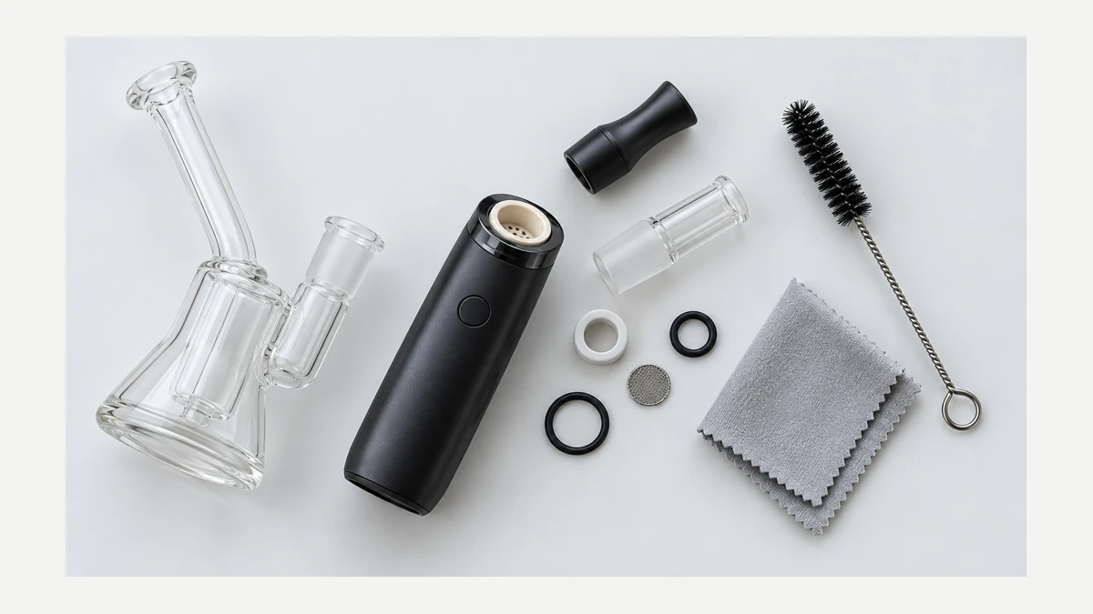
Joint wear is the other long-term factor worth watching. Ground-glass joints rely on a snug, slightly frictional fit to stay sealed; repeated disassembly for cleaning gradually smooths that friction down. A joint that used to hold firmly and now slides apart with light pressure isn’t necessarily damaged, but it’s worth checking whether it’s still sealing well enough to prevent air leaking in around the connection rather than through the intended path, which would show up as a noticeably easier, weaker-feeling draw with less bubbling activity than before.
⚖️ 5. Reading a Setup by Its Joints
Once each zone is identified, any concentrate-and-bubbler setup can be read the same way: trace the path from the heater’s output joint, through whatever adapter bridges it to the water chamber’s inlet, down through the downstem to confirm whether it sits below the waterline, across the percolation feature if there is one, and out through the mouthpiece. Fit problems almost always trace back to a mismatch at one of those joints rather than a flaw in the glass itself, and draw or throat complaints almost always trace back to percolation density and water fill level rather than the heater.
The practical habit worth building is checking joint size and gender before checking anything else — male or female, 14mm or 18mm, and whether an adapter is bridging a 510 thread to a glass joint — because that single check resolves most fit questions before they turn into a returned or mismatched piece of hardware.
🧼 6. 🧩 Map the System as Five Connected Zones
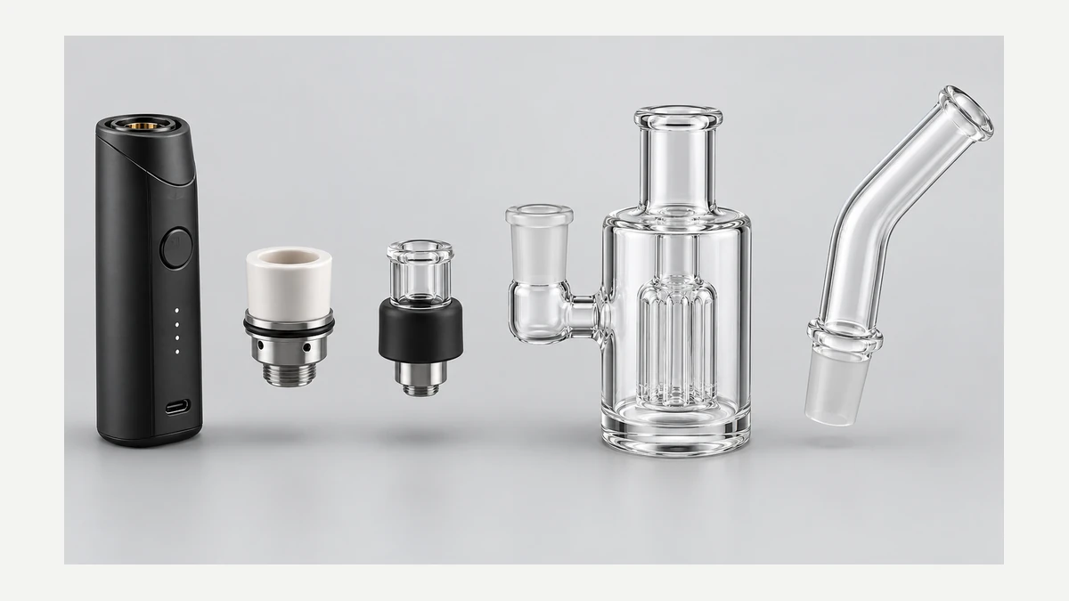
A concentrate vaporizer with a bubbler is easiest to understand as five zones: loading chamber, heater, adapter, water chamber, and mouthpiece. The device produces aerosol before it reaches the glass. The adapter must then carry that flow into the bubbler without leaking, collapsing, or placing side load on the heater connection.
This boundary distinguishes the format from an e-liquid tank. A loadable concentrate chamber is opened for material placement and cleaning; it is not a transparent reservoir with a wick. Product photos should show that chamber and the adapter clearly so the hardware category is not left to guesswork.
🔍 6.1. 🌬️ Every Added Seal Changes Draw Resistance
The dry device has its own inlet and internal airpath. Adding an adapter, water inlet, diffuser, and longer mouthpiece increases the number of restrictions. A very fine diffuser may look elaborate but can demand more draw than the device was designed around. Test the clean, empty connection with a normal pull and listen for leakage around every seal.
Water level matters for the same reason. Cover the intended diffuser openings, then stop. Extra water raises resistance and increases splash risk. Because compact bubblers have a narrow useful fill range, small additions should be checked with a dry pull rather than estimated from a product photo.
🧲 6.2. 💧 Condensation Creates Separate Cleaning Zones
The chamber and adapter collect condensed material before the glass sees it. The bubbler collects moisture and additional condensate downstream. These zones should come apart without forcing the heater or electronic body under water. A removable glass section, replaceable seals, and straight brush access make routine service easier.
Let glass and seals dry completely before reconnecting them to the powered device. If the adapter contains an internal bend that cannot be inspected, treat it as a replaceable service part rather than assuming a clear exterior means a clear airpath.
🔍 7. ✅ Compatibility Requires More Than Matching Diameter
Confirm the device model, intended adapter, joint size, support point, and assembled orientation. A joint can fit yet leave a top-heavy device hanging sideways from thin glass. Stable designs transfer weight into a base or cradle instead of asking the connector to carry the entire load.