A surprising amount of confusion around 510 thread batteries starts with a single number on a screen. Someone switches from an older, unmarked pen to a device with a digital voltage readout, sets it to a number that “worked” on a different battery, and gets a noticeably different result. Others run into the opposite problem: an LED-only battery with no screen at all, trying to decode blinking colors instead of digits. In both cases, the display is only reporting one small piece of what’s actually happening inside the circuit. Understanding what a screen can and cannot tell you requires looking past the number itself and at the hardware producing it.
🧭 1. What the Digital Display Actually Measures
A digital 510 thread battery’s screen typically shows a voltage setting, sometimes alongside a puff counter or a battery percentage. That number is a target the regulating circuit is instructed to hold at the output contact, not a direct measurement of what the connected cartridge is actually receiving at any given instant. The screen reflects a setpoint, and the circuit does real-time work to try to keep output close to it.
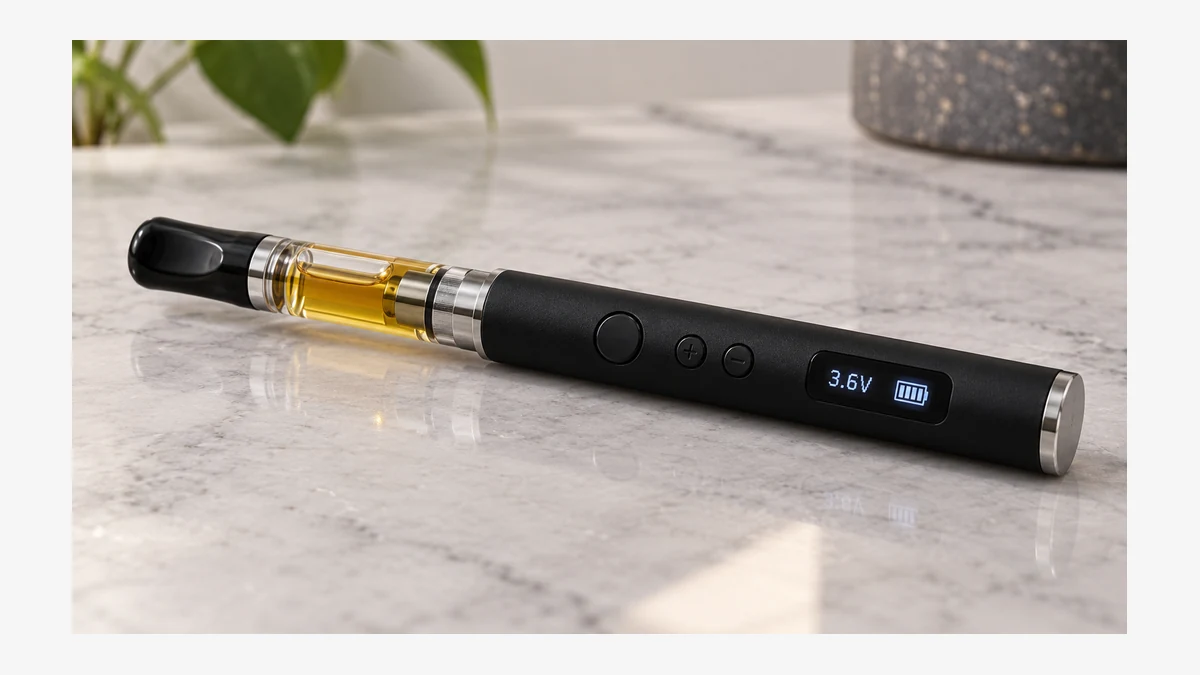
📐 1.1. Voltage Setting vs. Delivered Power
Voltage and power are related but not identical, and this is where a lot of the terminology confusion begins. The battery can only control the voltage it sends; the actual power delivered to the heating coil depends on the coil’s electrical resistance, which the battery does not display and often cannot measure precisely. Two coils with different resistance values will draw different amounts of current at the exact same voltage setting, which means the same number on the screen does not guarantee the same experience from one cartridge to the next.
This is a basic relationship worth keeping in mind:
- Higher resistance at a fixed voltage draws less current, generally producing a gentler output.
- Lower resistance at the same fixed voltage draws more current, generally producing a stronger output.
- The displayed voltage number stays the same in both cases, even though the result at the coil is different.
None of this is printed on the screen, so the display alone can’t explain why a setting feels inconsistent across cartridges.
For related component context, see the vape screen display guide.
🌬️ 1.2. Why the Same Number Can Feel Different
This also explains a common point of confusion: a user sets a battery to a specific voltage, switches cartridges, and assumes something is wrong with the battery because the sensation changed. In most cases, the battery did exactly what it was told — it held the same voltage. What changed was the resistance of the new cartridge’s coil, an unseen variable that the display has no way to report. A digital number is precise about one variable and silent about everything else in the circuit.
🔥 2. Connector Condition and Readout Accuracy
Before any voltage reaches a coil, it has to pass through a physical connection — the 510 threading and the center pin. This mechanical interface is a common source of problems that get misread as electronic or battery failures, partly because the screen has no way to flag a loose or dirty connection as its own category of issue.

🧩 2.1. Threading, Contact Pins, and Fit
The 510 standard defines a common thread pattern, but manufacturing tolerances, pin height, and spring tension vary between batteries and cartridges. A cartridge that threads on loosely, sits slightly crooked, or has a center pin that doesn’t make firm contact can cause an intermittent or weak connection even though the battery’s screen shows a normal voltage setting. The display reports what the circuit is set to output; it generally does not verify that the full circuit, including the physical contact point, is complete and stable.
Buildup is another factor. Oxidation, residue, or debris on either the battery’s center pin or the cartridge’s base can add resistance at the connection point itself, separate from the resistance of the coil. This added resistance sits between the battery’s regulating circuit and the coil, so the battery may still display its intended voltage while less of that voltage actually reaches the heating element. Keeping both contact surfaces clean and checking that a cartridge threads on straight and snug addresses a meaningful share of “weak hit” complaints that have nothing to do with charge level or battery age.
🔍 2.2. Cartridge Resistance as a Hidden Variable
Cartridge coil resistance is rarely printed on the cartridge itself, and even when a nominal resistance is specified by a manufacturer, actual values can vary between production batches. Combined with connector condition, this means two visually identical cartridges can behave differently on the same battery at the same voltage setting. A digital screen cannot see inside the cartridge, so it cannot account for this variation in what it reports.
For related component context, see the 510 battery color meanings guide.
🧼 3. Charge State and What the Battery Icon Hides
Battery level indicators, whether a percentage, a bar graph, or a colored LED, are also simplifications. They’re generally derived from the battery’s open or resting voltage, measured when the circuit isn’t actively under load, and translated into a simplified scale.

⚙️ 3.1. Voltage Sag Under Load
Lithium cells don’t hold a perfectly flat voltage as they discharge, and their voltage also dips temporarily the instant current is drawn — a behavior known as sag. A battery can display a comfortable charge percentage while resting, then show a brief, real drop in voltage the moment a cartridge is engaged, because internal resistance in the cell increases somewhat as charge is depleted and as the cell ages. This is a normal electrochemical property of the cell, not a malfunction, but it’s part of why output can feel weaker late in a charge cycle even when the resting percentage still looks reasonable.
A regulated circuit tries to compensate for sag by adjusting internally to hold the displayed voltage steady, but there are limits to how much compensation is possible as the cell’s available voltage drops toward its lower operating threshold. Near the bottom of a charge cycle, output can decline even if the setting on the screen hasn’t changed.
🧱 3.2. Error Messages and Protection Circuits
Digital batteries usually include a protection circuit that watches for short circuits, excessive current draw, or no-load conditions, and many will flash an error indicator or a specific LED pattern when something falls outside expected parameters. This is a safety feature, not a diagnostic report. An error reading generally tells you that the circuit detected an abnormal condition and stopped delivering power; it typically does not tell you whether the cause was a shorted connection, a damaged cartridge, debris in the threading, or an issue with the cell itself. Treating an error code as a precise diagnosis, rather than a prompt to check the physical connection first, is a common source of unnecessary frustration.
For related component context, see the adjustable-voltage 510 battery guide.
💧 4. Reading the Whole Picture, Not Just the Number
None of this means digital displays are unreliable — they’re genuinely useful for holding a consistent voltage setting and giving a rough sense of remaining charge. The key is recognizing which questions a screen can actually answer and which ones require checking the hardware directly.

| What the display can tell you | What it generally cannot tell you |
|---|---|
| The voltage the circuit is set to target | The actual power reaching the coil |
| An approximate resting charge level | How much voltage will sag under active load |
| That a protection circuit was triggered | Which specific physical fault triggered it |
| That a connection exists well enough to power on | Whether that connection is fully clean and firm |
When output feels inconsistent, it’s worth working through the physical variables in order before assuming the electronics are at fault: check that the cartridge threads on straight and snug, inspect both contact points for residue or corrosion, note whether the behavior shows up right after charging or mainly near the end of a cycle, and only then consider whether the coil resistance of the cartridge itself has changed. The number on the screen is a useful reference point, but it’s the connector, the coil, and the cell underneath it that actually determine what you feel.
🧲 5. Read the Screen as a Status Window
A display may show selected voltage, remaining charge as bars or a percentage, puff duration, a counter, resistance, or a short error code. Those fields are not universal. The first question is therefore not “what does this icon usually mean?” but “which field does this model document?” Two batteries can use the same small symbol for different states.
Selected voltage is a setting. It is not proof that the same voltage remains at the cartridge throughout a draw. Battery charge, protection limits, connector resistance, and the load itself can change actual behavior. A screen is useful because it exposes the requested state and some diagnostic information; it does not turn a compact battery into calibrated test equipment.
📏 5.1. Battery Bars Are Estimates
Small devices normally infer remaining charge from cell voltage and firmware rules. The bars can fall faster under load, recover after rest, or change in coarse steps. Treat them as a planning indicator rather than a measurement of exact remaining sessions. If the device shuts down or reports low charge while the icon still shows capacity, connector condition and the cartridge load deserve attention alongside charging.
🔌 5.2. The 510 Connection Adds Its Own Variables
The center contact carries one electrical pole while the threaded body carries the other. A film on either surface adds resistance, and an over-tightened cartridge can depress a spring-loaded contact far enough to interrupt connection. Clean only with the battery powered off, keep liquid away from the electronics, and let the connector dry before reassembly.
A “no atomizer,” “short,” or similar message describes what the battery senses at the connector; it does not identify one guaranteed failed part. Test with a known compatible cartridge only if the manufacturer permits it, inspect the threads and contact, and stop using hardware with damaged insulation or a loose connector.
🔋 5.3. Controls Must Match the Display
Some screens wake with the fire button, others illuminate only during adjustment or charging. Plus and minus buttons may change voltage in fixed steps, while a single-button model may cycle presets. An accurate guide needs the button sequence and the displayed unit together. A number without a unit, or an icon without a documented state, should not be expanded into an invented feature.
🖥️ 6. A Useful Display Reduces Ambiguity
The best screen is not necessarily the largest. It is the one that labels the selected setting clearly, distinguishes charging from operating state, and pairs errors with documentation. Read it alongside the connector, cartridge, controls, and device manual. That combination explains more than the screen alone.
Charging information needs the same restraint. A battery icon can show that charging is active without proving charge rate, cell health, or remaining time. Use the documented cable and input, keep the connector area dry, and investigate unusual heat or repeated errors instead of treating a changing icon as a complete diagnosis.
Likewise, a puff counter records button or draw events according to firmware; it does not measure material consumed. Counters can reset and may include accidental activations. They are useful for observing device behavior, not for making health or dosing conclusions.
If the display is dim, segmented incorrectly, or unreadable while the housing is otherwise intact, do not infer the active setting from the last remembered number. Power the unit down, consult the model-specific reset instructions, and keep it out of service if the selected state cannot be confirmed.