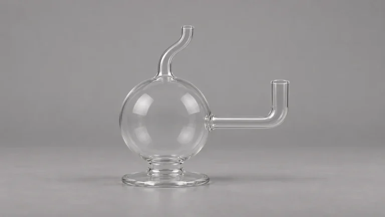
A globe dab rig gets its name from its round glass chamber. The name leaves three details open: the kind of side joint it has, the route through the chamber, and the part of the base that actually touches the table. Those details are easy to miss in a photo framed around the globe. Check the profile, the foot and the internal connections as separate features.
🔵 1. Identify the Globe in the Full Profile
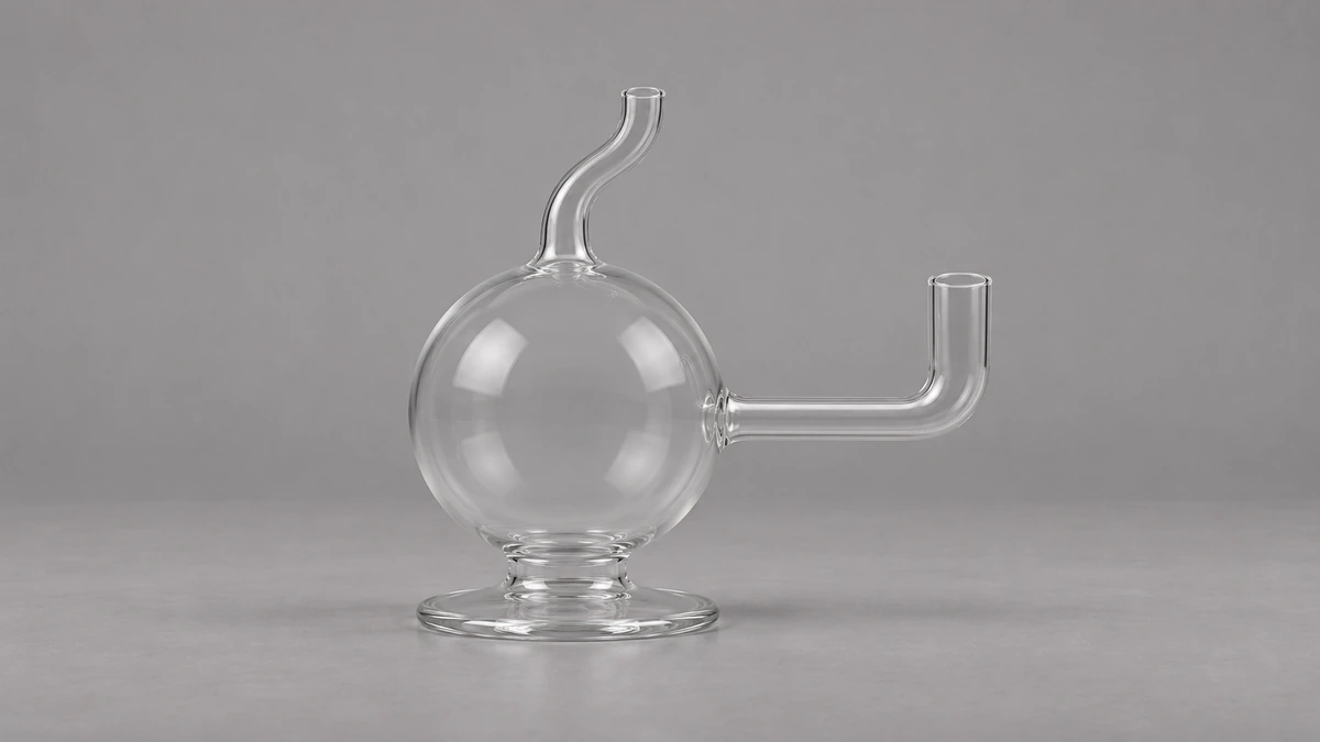
In a typical listing, the globe is the large round section between the inlet and the mouthpiece. It may look like a nearly complete sphere or a rounded vessel flattened where it joins another piece of glass. Start with an uncropped image. The outline of the main chamber becomes clear when the inlet, mouthpiece and base are all visible around it.
The word “globe” describes that outline. For example, one maker’s globe listing names the shape in the product title and lists the joint and the insert percolator separately. Those fields describe that particular piece. Another model with a round exterior can have a different joint, tube layout or foot.
📷 1.1 Compare Two Views of the Same Piece
A side view can make the globe easy to recognize, while an angled view reveals which tubes project toward the viewer and which pass behind the chamber. Before comparing two pieces, confirm that each pair of views shows the same model. Similar curves and colored details can recur across a maker’s catalog, especially when the same chamber style appears in more than one size.
If a retailer posts only a cropped photo of the sphere, use that photo to describe the silhouette. Leave the height, base and joint position open. A wide view from tabletop height is more helpful for those questions than a close view taken from above.
🔗 2. Read the Joint as Its Own Component
Follow the visible glass arm that leads from the side of the globe to its open end. In a drawing, that end may be labeled the joint or socket. The opening, angle and location of the joint are features of the arm, and the arm can meet the chamber at different points. Two round bodies can therefore have similar silhouettes and different fittings.
Record the joint size and style from the maker’s specification when one is available. A photo can locate the joint, but perspective can hide its taper or make an opening appear larger. If you cannot see the rim, note which part of the image is obscured. A labeled side view or the model’s parts drawing may answer the question without any trial fit.
📐 2.1 Pay Attention to the Direction of the Opening
The position where a glass arm leaves the globe and the direction of its opening are different observations. A tube can start low on the side and bend upward before it reaches the joint. A straight arm on another piece might start at the same height but point diagonally. To describe either one, write where the arm starts and where the opening faces. The dab rig adapter guide explains the separate roles of joint size, style and angle.
🌀 3. Follow the Visible Route Through the Glass
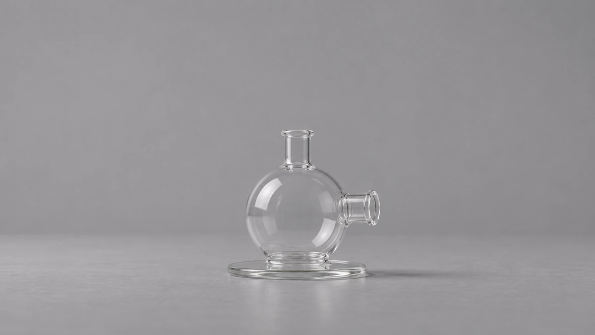
Clear glass lets you see several parts at once, including some on the far side of the chamber. Begin at the externally visible inlet and follow the connected glass tube as far as the photo allows. Locate the outlet at the other end by working backward from the mouthpiece. If you cannot see where two sections meet, leave that connection open until you find a second view or a maker’s diagram.
A fixed internal component can be visible inside a globe without protruding outside it. When the maker identifies a diffuser or percolator, its diagram may show a tube or openings near the bottom of the chamber. Its shape and location come from the specific build. The same outer sphere could enclose a tube that enters at another height or ends in a different shape.
🧩 3.1 Recognize an Optical Overlap
A clear tube may appear to cross another tube in a flat photo. That crossing alone does not establish a physical junction. A second photograph taken from another side can show whether one passage is in front of the other. Look for a continuous glass wall at the apparent join. If reflections obscure the wall in both views, a drawing is better evidence than the single image.
External loops make this problem especially visible. A loop drawn from the side can disappear behind the globe in a front view. The mini recycler guide gives names to visible side loops and return paths. Use those terms only when the part can be seen or the manufacturer identifies it.
🧱 4. Look for the Foot That Meets the Table
The broadest part of a globe is often well above the surface that supports it. The foot may be a flat disc fused beneath the chamber, or it may be a flattened lower section with a visible contact ring. A curved outside wall can continue toward the table without touching it across the entire lower curve. An image from tabletop height shows which glass extends down to the supporting surface.
When the glass is empty, cool and already resting on a clear level surface, look at the contact area without pushing the rig to test it. Watch for a gap on one side or for an object caught beneath the foot. If the piece is visibly damaged or cannot stand steadily, describe the issue and consult the maker before handling it further.
⚖️ 4.1 Distinguish the Chamber Width From the Foot Width
Suppose two photos list the same overall body width. In the first, the globe extends sideways beyond a narrow foot. In the second, a flat disc extends beyond the chamber. The published overall width could refer to the round wall in one case and to the disc in the other. Ask which surfaces were measured before treating the two values as interchangeable.
A wider foot gives a piece a different supporting area, but shape and width alone do not establish stability. Weight distribution, the actual contact surface and parts attached away from the center all matter. Describe the piece as pictured and keep any added parts separate in your notes.
🧪 5. Compare Two Hypothetical Globes
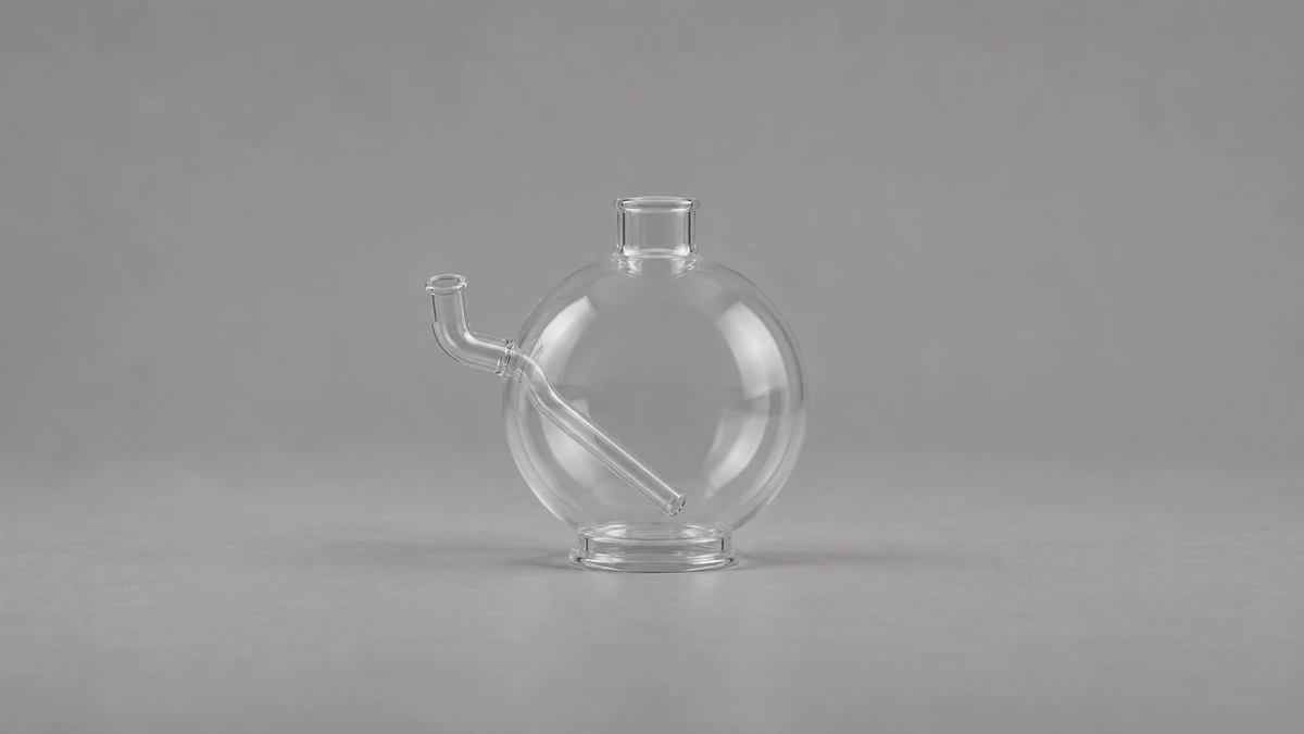
Imagine a pair of empty rigs with the same round exterior. Both have a short neck and a glass arm projecting from one side. A photograph that crops away the lower third makes the two shapes appear interchangeable. Once you see the whole pieces, the differences become easier to describe.
🔍 5.1 Globe A Has a Narrow Foot and a Low Internal Tube
Globe A stands on a small circular foot. Its glass arm turns upward outside the chamber. Through the globe, you can see the tube that continues inward and ends near the bottom. A side view lets you trace the tube to the arm. The front view shows the opening but does not reveal the angle of the whole arm.
For a support question, the most useful detail might be the open end of the joint and the visible tube behind it. Take a second photo low enough to include the foot. Together the photos show which features belong to the outside fitting and which belong to the fixed glass body.
🧭 5.2 Globe B Has a Separate Disc and a Different Side Arm
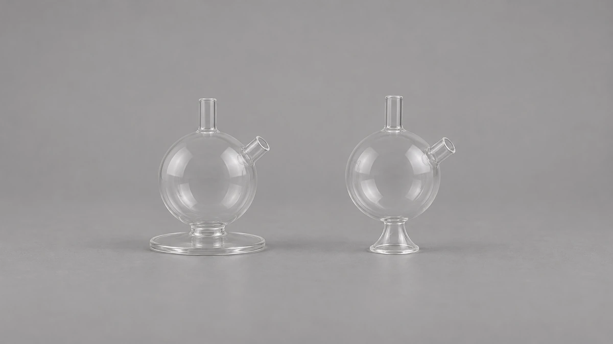
Globe B rests on a separate flat disc wider than its bottom seam. The external arm meets the sphere in a higher position. The arm leads into a fixed tube, but reflections hide where it ends in the first photo. The widest dimension and tube position cannot be copied from the Globe A notes.
Ask for a second angle that shows the inside end of the tube. If the maker provides a diagram, match it against the joint, disc and mouthpiece in the full exterior photo. The outside curve identifies the style of both pieces. The visible route and actual foot give you enough detail to tell them apart.
💬 6. What a Wobble Report Can Tell You
In one owner discussion, a reader asked what to do about a wobbly rig. Two other discussions started with rigs that tipped or felt less stable after an accessory was added. These posts cover different pieces and do not establish a defect shared by round glass. They illustrate why the first question should be whether the issue is visible in the bare glass body or only when a side component is attached.
For a report about bare glass, write down whether the foot rocks, whether the surface is level, and whether the full contact edge is visible. For a report about a separate accessory, use a photo of it beside the glass body and mark the side where it belongs. That record gives the maker a way to distinguish the base problem from a question about the arm or the attachment.
🗂️ 6.1 Keep General Fit Advice in Its Place
A compact rig guide can help name features such as the body height, joint and clearance around the base. AOVAPE’s small dab rig guide covers that broader format. For a globe-specific description, add where the foot lies relative to the widest part of the round chamber. If a maker uses the same silhouette with multiple base styles, that extra observation can help identify which design appears in the photo.
📝 7. Build a Useful Record of the Exact Piece
Start with the name as printed on the package or listing. Record the model code if one is provided. Add a full profile and a view that shows the inlet and mouthpiece in the same frame. A low image of the base can establish which part is resting on the surface. If a fixed tube is visible, record where it appears to start and stop.
For individual part names, the dab rig component map distinguishes the fixed body from removable pieces. Use the maker’s name for an exact part and a descriptive phrase for an unlabeled one. “The fixed tube visible behind the side joint” is more useful than assigning a specific diffuser name based on a lookalike photo.
📋 7.1 Give the Maker One Question at a Time
Separate the missing information into individual questions. If a listing says “globe” but does not identify the joint, ask for the joint specification. If the base is out of frame, request a full side photograph at table height. If the product photo shows a feature inside the sphere without naming it, ask for the corresponding drawing or another view. A specific question gives the maker something concrete to confirm.
When the reply arrives, save it with the exact model and image it refers to. A later listing may use the same name for a different joint or foot. Keeping the identification tied to the visible parts makes the record useful when you compare those listings again.
🧾 8. Read Dimensions Against the View That Supports Them
A parts photo often puts the globe in the center, with a detachable component shown beside it. The stated height may refer to the bare body or to the assembled configuration in another photo. Record which one is pictured and ask what the published dimension includes. A measurement that ends at the top of the mouthpiece answers a different question from one that ends at the top of an attachment.
📏 8.1 Match Each Dimension to a Feature
Use a front or side drawing with dimension arrows when the maker supplies one. For a body-width dimension, look for whether the arrows stop at the globe, the foot, or the furthest point of the side arm. A wide side joint can extend the outline of the assembled piece without adding tabletop support. The maker may list separate dimensions for the body and the base. Keep both instead of copying one value into the other field.
Where no dimensions are available, use relative descriptions such as “disc extends beyond the widest glass wall” or “side arm projects beyond the disc.” This makes the note understandable without pretending a photo gives a scale. If a listing combines photos of several color or size variants, confirm the exact variant before adding any numbers.
🔖 8.2 Separate a Product Photo From an Exploded View
An exploded view may place a removable piece beside a socket to identify it. A product photo can place the same pieces next to each other simply to show the contents. Check the labels before treating either arrangement as an assembly drawing. If the joint is visible but the adjacent piece is unnamed, you can still record the location of the socket and the outline of the loose part in separate fields.
Keep the annotated record with the original photograph. It should tell the next reader which shapes were observed directly, which were confirmed by documentation, and which still need an answer from the maker.