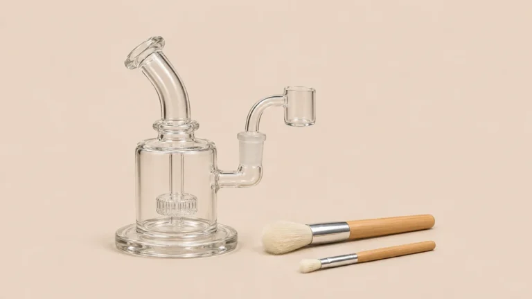
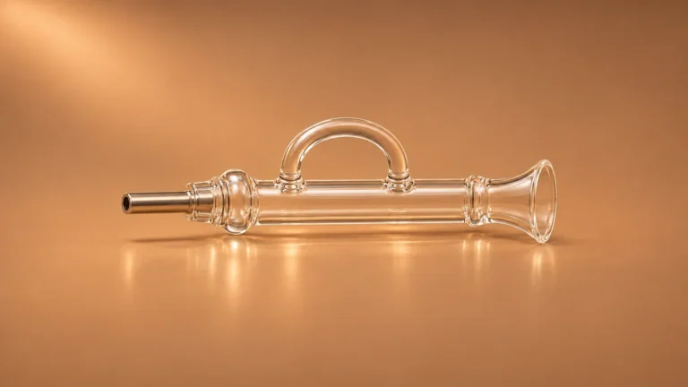
The parts of a dab rig fall into two groups: features of the main glass body and separate pieces that meet it at an interface. To describe a part accurately, start by locating it. A tube inside the main chamber, the socket on its exterior and the narrow neck of a detached attachment may look continuous in a side photograph. They describe three different locations, and the manufacturer’s parts drawing can show which belong to the same assembly.
🧭 1. Map the body before naming the loose parts
Start with the base, main chamber and mouthpiece. These are useful landmarks even when the silhouette looks unfamiliar. The base is the part that supports the assembly on a surface. The main chamber is the enclosed volume above it, and the mouthpiece is the outlet at the end of the neck. A flared lip may make the outlet easy to spot. On a curved design, the outlet can face sideways, so it helps to trace the neck rather than identify the mouthpiece by height alone.
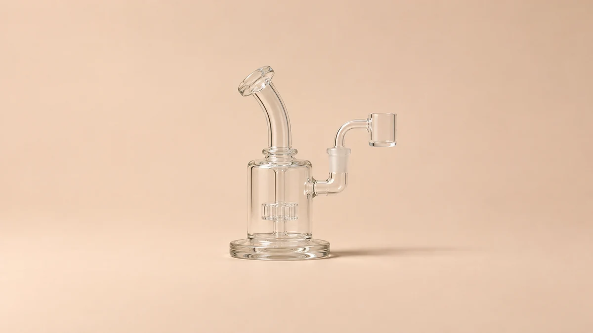
A photograph can show the position of an opening or the shape of a foot. It generally cannot establish the service history of the piece or whether an apparent line is an assembly boundary. A decorative color change, a molded ridge and a fused join can all interrupt the outline. If you are labeling a photo, first describe the visible shape, then compare it with the construction shown in the maker’s documentation.
🔗 2. Separate the socket from the tube behind it
The receiving joint is the interface where a separate attachment meets the body. The downstem is the tube continuing into the chamber. The two labels answer different questions: where the attachment meets the body, and where the internal path goes from there. Some designs integrate the tube into the body. Others document it as a distinct part. For example, one GRAV glass body lists both a fixed downstem and a female joint. Those labels describe separate features on that model.
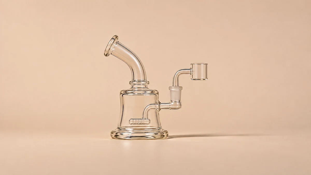
A discussion about a dropped rig shows how easily names get crossed. The owner called the broken area an adapter, and a commenter referred to the downstem section. For identification, the useful detail is the location of the break relative to the socket and main chamber. Another poster explicitly identified their broken downstem as fixed. A visible fracture does not turn that feature into a separately replaceable part. Refer to the maker’s diagram and leave damaged glass undisturbed.
📐 3. Describe a detached component from end to end
A detached banger can be described by its bucket, neck and mating end. Its neck may look like the beginning of the internal tube when the two are aligned in a photo. Keeping the detached piece in a separate frame makes the distinction clearer. A reader who broke the narrow section of an attachment described it as a down spot. Naming the neck and mating end separately gives someone reading that description a more precise starting point.
Related reading: broken glass attachment.
Specifications can help identify which end you are describing. A manufacturer listing for a quartz component identifies a male joint and a 45-degree neck as separate attributes. A nominal size printed beside a joint identifies one characteristic. The shape and angle are separate information, and the manufacturer’s documented fit remains the relevant reference for a particular assembly.
🔍 4. Trace the interior from the inlet
Once you know which opening accepts the attachment, look at what continues from it inside the chamber. In a simple drawing, the downstem is the line leading away from the inlet. The percolator is the feature that divides that path into outlets. These functions can share one piece of glass. A stem that terminates in several openings can serve both roles, so two labels on a diagram do not necessarily mean two separate pieces.
🗺️ 4.1 Follow the Outline in a Diagram
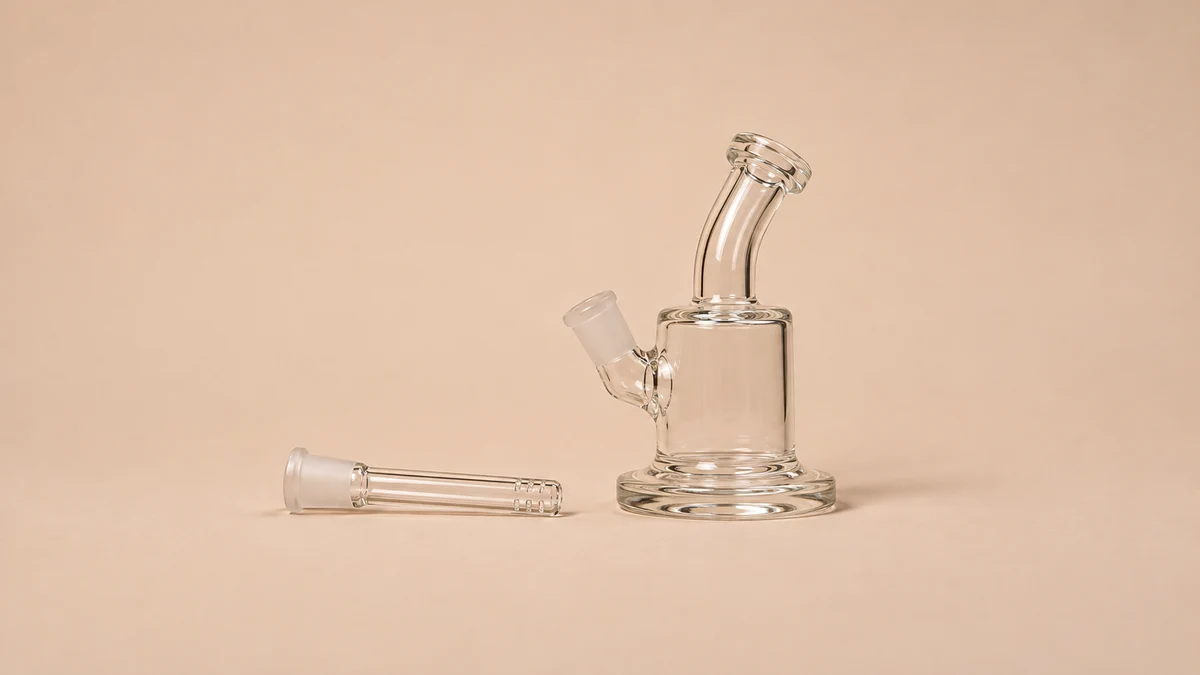
One useful way to read a diagram is to cover its labels and follow only the outlines. Can you trace a tube from the receiving joint to a set of outlets? Does another tube continue to a second chamber? Is the long neck on the opposite side the path to the mouthpiece? The answer might be obvious in a section drawing and uncertain in a three-quarter product photograph. Clear glass adds reflections and overlapping edges, particularly when there are several tubes behind one another.
Suppose a picture shows a disk and a narrow vertical tube. It would be premature to call the disk a screen or the tube a removable stem. Look for a second angle or an exploded view with separate part numbers.
🧩 4.2 What an Exploded View Can Confirm
An exploded view can show that the tube and disk belong to a single assembly even though the photograph makes them look like independent objects. A diagram of the interior is useful for the route. A parts list is more useful for understanding what the maker treats as a replaceable component.
🫧 5. Distinguish a passage from the shape around it
Some glass bodies are easy to describe from the outside: a broad chamber below, a neck above and a joint off to one side. Others use a compact shell with narrow passages visible through its wall.
The largest visible shape is still a useful landmark, but its outline does not tell you where each passage goes. A side tube might connect two points on the same body, while the neck at the top may simply end at the mouthpiece. Those are distinct paths even if they overlap in a front view.
Imagine taking a front photograph and a side photograph of the same empty piece. In the front image a narrow line seems to end halfway down the chamber. From the side it becomes clear that the apparent endpoint was hidden behind a wider tube. That is a reason to write “visible side tube” in the first caption and reserve more specific language for the second image or drawing. It also explains why identifying a design by counting visible tubes can lead to inconsistent descriptions across listings.
Use the same discipline for the outer glass. The rounded edge at the bottom might be the rim of a broad foot, or the body might transition directly into a flat base. Either shape supports the assembly. A decorative sleeve or stand shown nearby deserves its own label if it is separate. The article on small dab rigs is a useful companion for stability questions. Here the task is narrower: identify which surface is the support and where the glass body begins.
🧷 6. Keep the cap and adapter in their own categories
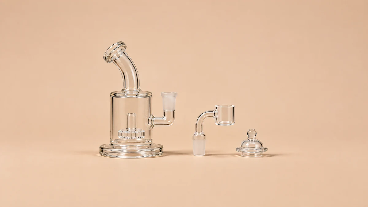
A cap belongs with the opening at the top of a separate bucket. An adapter belongs at an interface between components. These descriptions refer to position, not to what the accessories look like. A small rounded accessory might be recognizable in a full assembly drawing, but a close crop of its rim may omit the only feature that identifies it. When several pieces are pictured together, name each piece before treating the whole set as a single part.
Related reading: joint adapter.
🔎 6.1 Identify the Piece Between Two Interfaces
Consider an unlabeled photo with a body, a separate bucket and a small glass component between them. If the middle component has two mating ends, it may be shown as an adapter. Check the inventory before assigning that name. Some photographs include a loose downstem that also has an obvious mating end. The useful distinction is whether the piece is shown bridging two external interfaces or extending into the chamber. If the photo leaves that uncertain, the supplier’s diagram is a better reference than resemblance.
📍 6.2 Describe the Cap by Its Position
A cap can also have features that are easy to overread in a photograph. A protrusion might be a handle or a visible extension of the cap itself. A close-up can establish its outline. It cannot establish that it matches every bucket with a similar opening. Keep the cap’s visible form separate from any documented fit claim. The existing AOVAPE guides to carb caps and dab rig adapters address those more specific fit questions.
📝 7. Describe a part so someone else can identify it
When asking someone to identify a part, start with which object it belongs to and where on that object it sits. “The socket on the side of the main glass body” is more precise than “the connector.” “The neck on the detached quartz component” is more precise than “the stem.” Both descriptions make sense without a photograph. If a photograph is available, label the area in a copy while retaining the uncropped original so the reader can see its relationship to the chamber and base.
Related reading: cap geometry.
🏷️ 7.1 Record the Part Name and Revision
Include a manufacturer part name or model revision if you know it. Two versions can share a product name and still have different parts lists. Separate what you observed from what the drawing confirms. For example, “I can see a line just below the socket. The parts diagram shows the tube as part of the body.” This says exactly how the conclusion was reached. If there is no diagram, leave the construction unresolved and describe the line by location.
✍️ 7.2 Write a Description That Locates the Damage
For a hypothetical report about damaged glass, a useful description might read: “The detached bucket is intact. The visible damage is on the receiving side of the main body, below the opening.” That is enough to distinguish the affected assembly without attempting to move the glass. For a photograph of intact hardware with several loose pieces, start with the upright body and describe the other objects separately. The same wording works for an inventory, a caption or a support question.
Finish with the point of uncertainty. If you can name the opening but cannot tell whether the internal tube is separate, state that directly. A clear description of the location gives the manufacturer or a knowledgeable reader something concrete to check.
🗂️ 8. Read a parts list beside a photograph
Suppose a diagram assigns a single number to the body and shows the inlet and downstem on that same drawing. A second number points to a separate cap, and a third points to a detachable bucket.
For that specific drawing, the list supports calling the downstem a feature of the body and the cap and bucket separate items. The labels also tell you where to stop. A drawing that identifies the body as one item does not necessarily describe how the glassmaker fabricated it or whether a specialist can service it.
Now consider a second diagram that shows an independent tube below the attachment. The writer can use the same word downstem while describing a different construction. The difference becomes clearer if the caption says which model the drawing represents and what the part list actually names. Avoid using one diagram to label every glass body of a similar shape. In an article or support exchange, the useful sentence identifies the construction of the pictured example.
A practical photo set can make that reasoning easier to follow. Use one full view to establish the base, body and outlet. Use a second view to show the inlet in relation to the interior tube. If there are already loose pieces, photograph them together on a separate surface. This captures the relationship between the components without asking anyone to detach a stuck or unidentified piece.
The same approach helps when documentation uses a different term. A maker may call an entire part a glass assembly while a reader calls its visible tube a stem. Record both names with their scope. The first names the item in the parts list, while the second names the feature the reader can see. That distinction preserves the vocabulary people search for and still lets another person find the correct drawing.
When a photo and a parts drawing seem to disagree, check that they describe the same assembly state. A photo of the full rig may include a cap and adapter that are absent from a drawing of the bare glass body. Conversely, a drawing of the body may show the interior end of a tube that a camera cannot see. Put the images side by side and label them “assembled view” and “body only” before comparing the outlines. Then follow one component at a time. For example, if a photograph shows a sleeve around the inlet but the diagram labels only the inlet, record the sleeve separately and leave its part number open. This gives someone reviewing the drawing two distinct questions: whether the opening belongs to the body and whether the sleeve appears on the separate accessory list. It also makes it easier to identify which photograph would resolve the missing detail.