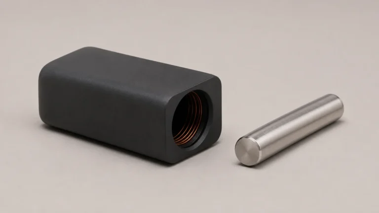
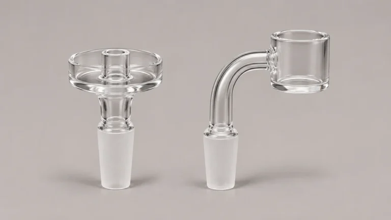
A mini electric dab rig can fit on a shelf and still require considerably more room when its glass has to come off. The base footprint describes the part that touches the shelf. Width and height with the glass attached describe the space the rig occupies while standing. The extraction path of a removable top and the space behind a connected cable describe two more boundaries. If you need to decide whether an existing shelf or case can hold the hardware, write down those boundaries separately. A single width and height cannot answer all four questions.
📐 1. Separate the Footprint From the Outline
The footprint is the space taken up by the feet or bottom of the base. Place the empty, unpowered rig on a level work surface, with its cable disconnected, and look at where the base meets the surface. A glass part can project farther sideways than the base. A rubber foot can sit farther inboard than the plastic or metal enclosure. It helps to sketch the contact outline and the widest outer outline as different shapes.
🗺️ 1.1 A Shelf Can Be Deep Enough for the Base Alone
Picture a shelf against a back panel. The base of the rig reaches almost to the panel, while the glass bends out toward the rear. From the front, the whole setup can look neatly centered even though the top touches the panel. Shifting the device forward frees the glass but changes how close the front feet are to the shelf edge. A side view explains what a photo taken straight on misses. It also tells you which dimension needs extra room.
The mini dab rig guide covers other ways compact hardware can differ from a larger design. An electric model adds its own enclosure and connection points. Whether the base is small says very little about where the upper assembly overhangs or how the cable exits.
🧩 2. Find the Largest Projection In Each View
Measure the widest point you can see looking from the front, then look down from above to locate front and rear projections. A sloping glass neck might set the front-to-back depth even if a controller housing is the widest part from the front. A tether may lie flat in the catalog image yet hang off the side in storage. Record which part sets the boundary so your notes still make sense after that part is removed.
📷 2.1 Use a Side View to Find Hidden Clearance
A photo of the side can show how a cap or glass neck extends beyond the body. Keep the lens roughly level with the part rather than looking down from above. If you include a ruler for scale, place it near the plane of the part being measured. A ruler closer to the camera makes the same object look smaller relative to the scale. For tight clearances, rely on direct measurements or a manufacturer’s dimensional drawing rather than measuring pixels.
A detachable top can also change the shape above the base when alternatives are documented for a specific model. A taller or angled top needs its own outline. The guide to dedicated dry tops and water glass shows why glass identity and glass fit are separate questions. Matching the clearance in an illustration does not establish that an alternate top fits your unit.
↕️ 3. Check the Removal Path Separately
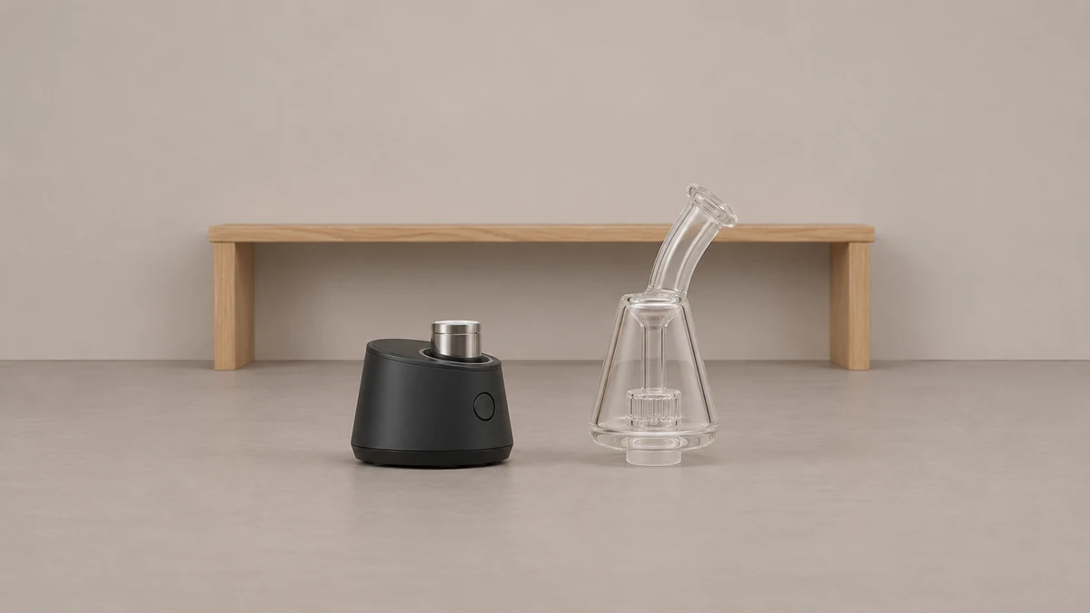
A removable part occupies more room when it is in motion. If the documented removal path starts with an upward lift, the open space above the assembled unit must accommodate that movement. The installed top might just clear an upper shelf and still have no room to lift. A glass design that clears the shelf when standing can also strike a lip on the way out, depending on where the gap begins.
🔎 3.1 Look for a Lip, Rail or Door Near the Top
Imagine a cabinet whose inside height sounds generous. A narrow strip across the front reduces the opening. The assembled rig appears to clear the cabinet in a side photograph, but the rail overhangs the space directly above the top. The important dimension is the open space directly above the top at the point of removal. The full cabinet height behind the rail doesn’t answer that question.
Some designs have removable glass. For example, the manufacturer’s XS knowledge base treats its glass attachment as a distinct part. That example shows why it can help to label the glass and base separately before comparing space. It does not establish the same removal direction, latch, seal, or top dimensions on a different model. The exact instructions for the device in hand are the source for any removal motion.
If the manual is unclear, note the obstruction and the part boundary on a drawing. Do not guess whether a stubborn part can tilt or rotate. A hardware photo can show that an intended path is blocked, but it cannot tell you whether another path is allowed. You can decide whether the shelf is suitable without testing a different way of handling the glass.
🔌 4. Give the Connector Its Own Space
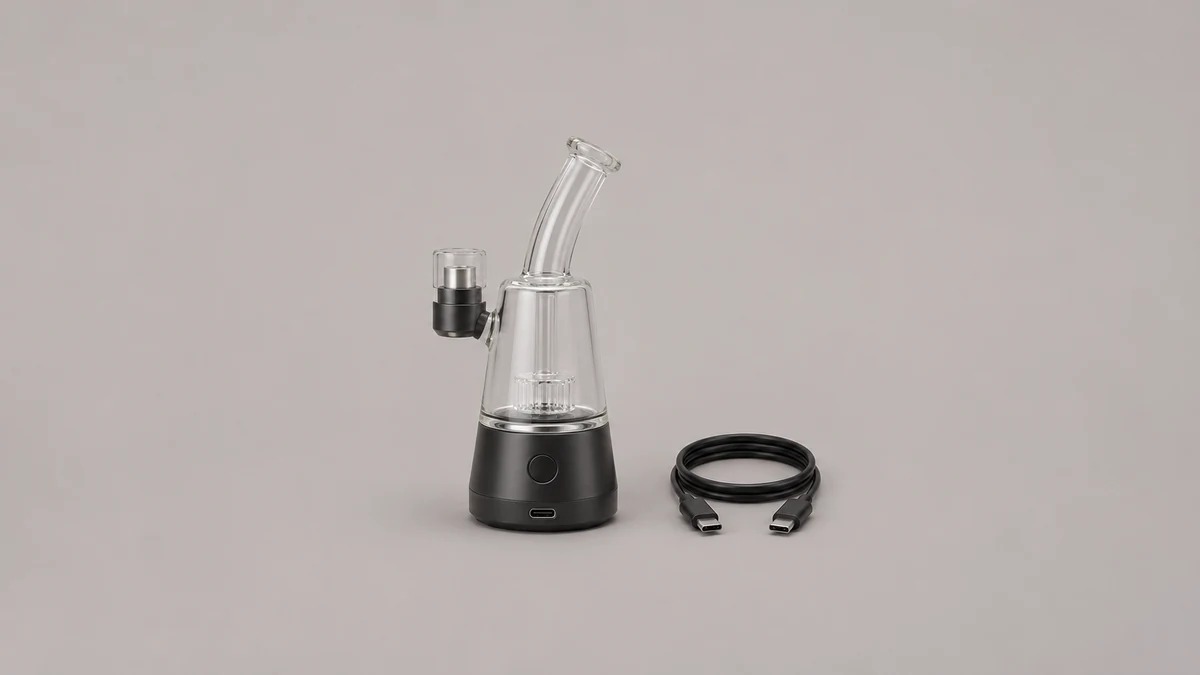
A cable can add depth even when its plug looks small. The connector shell protrudes beyond the enclosure, and the strain relief at the back of the plug takes up additional room before the flexible portion starts. A front-facing port moves this projection toward the walkway or door. A rear-facing port moves it toward the wall. Depending on how the base is set down, a side connector may make two nearby devices foul each other even though their bases fit side by side.
📏 4.1 Measure the Projecting Plug, Not the Port Recess
A recessed port is part of the enclosure and tells you where the plug attaches. It does not tell you how far that plug will project outside the enclosure. A photo of the connector you actually use can settle what a port photograph leaves unclear. With the rig and cable disconnected, hold the connector nearby in its expected orientation for reference. Keep the cable’s existing curve broad and let it lie on the surface, rather than bending it to prove it can fit inside a narrow gap.
The XS documentation names a USB-C connection on that model. The USB-C label describes the connector family. Look at the plug housing and strain relief separately when allowing room around the outside of the rig. If you plan to use the dimensions from a drawing, document which cable the measurement assumes. A shallow shelf that works with one plug outline may have less margin with another.

🧳 5. A Case Has a Different Set of Boundaries
A rigid case opening may look big enough while an internal seam, foam divider, or recessed hinge reduces the usable space. When the rig and glass are packed separately according to the manufacturer’s guidance, there are two different outlines to account for. The round base may fit a square compartment but leave room only in the corners, which can be too shallow or narrow for the top. The glass may have its own rim or stem that makes one side more prominent.
🧰 5.1 An Unconnected Cable Still Occupies Space
Treat a cable stored in the case as its own item. A zippered pocket inside the lid may look flat when it is empty, then project into the same area as the glass when it contains a cable. The plug is usually stiffer and more defined than the cable loop. Looking at the empty case from the side can help identify where those objects would overlap when the lid moves. The portable rig hardware guide covers other considerations when glass and accessories travel together.
There is a difference between clearing the opening and sitting fully inside the compartment. Lay out the parts beside the closed case and compare them with the usable internal dimensions, including the height of any dividers. Don’t read an external product dimension as empty air inside the case. If a compartment is irregular, record where it narrows, since the widest usable rectangle may be much smaller than the overall interior length and width.
📷 6. Make a Clearance Record From Three Views
A simple record can consist of a top view of the base, a side view of the assembled unit, and a view of the intended placement area. In the top view, mark the backmost and widest projections. In the side view, include a visible vertical reference and label the top in the installed position. In the area view, mark the shelf opening and any cable obstruction. Record the intended direction of the cable so a future reader knows which wall is the relevant one.
A fourth photo can keep the detached pieces in the record, if they have a separate storage space. A detached top lying on its side can have a larger length than you would expect from a front photo of it mounted upright. Conversely, dividing a case into two compartments can put the longest part against the short side of an internal divider. A picture of the widest part alone doesn’t reveal where that divider crosses the path.
🗂️ 6.1 Label the State of the Hardware
Use short labels such as base only, complete assembly, cable present, glass removal path, and packed separately. A listing’s stated dimensions may correspond to any one of these states. If a dimension is not identified, leave it unassigned until you can verify it. A manufacturer drawing, a photo showing a scale beside the exact assembly, and a case measurement answer different questions. Treat them as different observations instead of averaging numbers across sources.
Secondhand images deserve the same care. A generic photo might show a different glass attachment to communicate the overall product idea. A photo that has been cropped can also hide the point where the connector exits. If the exact glass used in a listing is unclear, a measurement derived from the photo won’t resolve which outline belongs to the hardware you have.
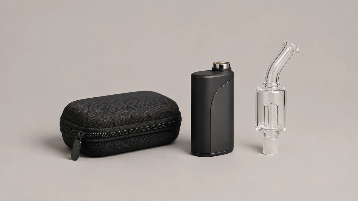
✅ 7. Compare the Same Rig in Three Places
On an open worktable, the problem may be an accessory that overhangs the area you marked for the base. On a low shelf, the same accessory may fit when installed but be unable to clear the front rail during removal. Inside a case, two parts may fit comfortably side by side while a full pocket in the lid takes up the same space. Each placement reveals a different boundary. A footprint that looks generous in the first situation cannot settle the other two.
💬 7.1 Describe the First Boundary That Fails
A precise question to a maker or support desk can say that the empty base fits completely on the shelf, the installed glass clears the opening, and the shelf above blocks the documented upward path. A different question can state that the whole assembly fits but the intended cable shell extends into the back panel. The first question concerns access and the second concerns depth behind the connector. Either is easier to answer than whether the model is small.
If the device is already on hand, keep the relevant measurement beside the place it represents. The full assembled height belongs next to the open shelf height. The required movement belongs next to the unobstructed space along its path. The plug and cable belong next to the chosen wall or edge. This is why a useful record of a compact electric rig usually has several dimensions even when a product page needs only one short line of specifications.
🗄️ 8. Plot the Actual Shelf Opening on Paper
A quick sketch can use four rectangles: the back wall, the side walls, the underside of the shelf above and the open front. On the front view, mark the location and width of any shelf lip. On the side view, mark how far that lip projects into the space. A door may add a second obstruction. Its handle or catch can occupy a strip of the opening even when the door swings away. A mark on the drawing lets you compare the actual opening and the internal cavity without assuming they are the same size.
Next, draw the base and the outline of the installed glass separately. If the documented path of a removable piece crosses one of the obstructions, write down which piece crosses where. The shelf could still work as a resting spot for the unpowered rig even when it cannot accommodate service access. That is a different statement from claiming all maintenance can occur in place. For a cabinet with no safe handling room, compare the clearance on a separate unobstructed surface.
📋 8.1 Record What You Didn’t Measure
If you only know the height with the supplied glass, say so. If a cable is missing, leave the connected depth blank. If you don’t have the directions for detaching the glass, the removal envelope is unknown. Recording those three uncertainties separately avoids treating the easiest number to find as the answer to a question the number can’t resolve.